
Coupling structure for a shell

a technology of coupling structure and shell, applied in the direction of sheet joining, fastening means, hook fasteners, etc., can solve the problem that the circuit design engineer is unable to achieve the goal of reducing a single centimeter in size, and achieve the effect of preventing untimely breakage enhancing the resiliency of the first and second hooks

Inactive Publication Date: 2011-10-06
GIGA BYTE TECH CO LTD
View PDF15 Cites 50 Cited by
  • Summary
  • Abstract
  • Description
  • Claims
  • Application Information

AI Technical Summary

Benefits of technology

[0013]Therefore, the object of the present invention is to provide a coupling structure for use in a shell that is free of the disadvantages, that includes hooks that bend in direction parallel to a horizontal side of the shell and that needs no barb configuration of the hooks.
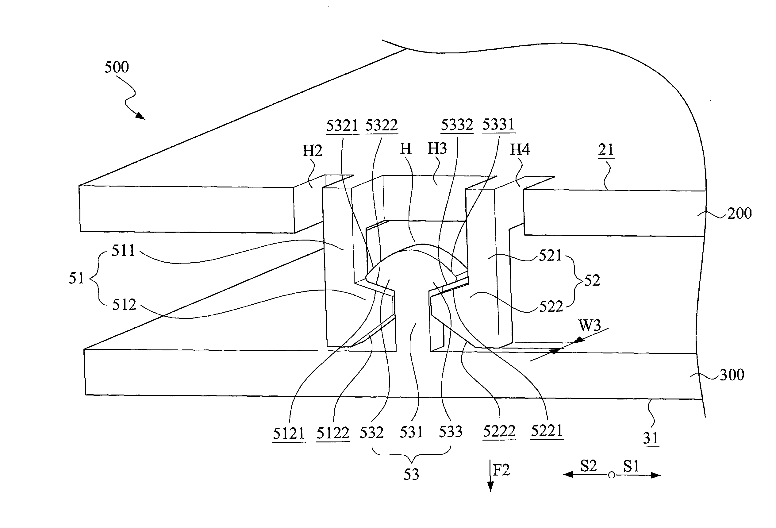
[0019]The first side of the first shell half is formed with at least two peripheral notches respectively adjacent to the first and second hooks and respectively opposite to the clamping space so as to enhance resiliency of the first and second hooks.
[0020]When the coupling structure of the present invention is compared to the prior art ones, the present coupling structure is used for coupling the first and second shell halves, and includes first and second hooks mounted to the first shell halves for clamping securely the two-way securing hook of the second shell half. Since the first and second hooks respectively have inner inclined face unlike to that of the prior barbed configuration, it is easy to detach the first and second shell halves.
[0022]In addition, the peripheral notches formed along the first side of the first shell half respectively adjacent to the clamping space provide enhanced resiliency of the first and second hooks, thereby preventing untimely broken of the first and second hooks.

Problems solved by technology

In many sophisticated electronics field, even a target to reduce a single centimeter in size is a challenging issue for the circuit design engineer.

Method used


Image

  • Coupling structure for a shell
  • Coupling structure for a shell
  • Coupling structure for a shell

Examples


Embodiment Construction

[0028]Referring to FIGS. 3 and 4, wherein FIG. 3 shows a preferred embodiment of a coupling structure of the present invention prior to coupling first and second shell halves into a shell while FIG. 4 illustrates the preferred embodiment of the coupling structure of the present invention coupling the first and second shell halves into a shell. As shown, the coupling structure 500 of the present invention is disposed between the first and second shell halves 200, 300 juxtaposed to each other for coupling the same into the shell, and includes a first hook 51, a second hook 52 and a two-way securing hook 53. The first shell half 200 has a first side 21. The first hook 51 includes an elongated first resilient section 511 extending from the first side 21 towards the second shell half 300 and a first clamping section 512 extending laterally from the first resilient section 511 along a first direction S1.

[0029]The second hook 52 includes an elongated second resilient section 521 extending ...


PUM


Abstract

A coupling structure for coupling first and second halves includes two hooks and a two-way securing hook. The first hook includes a first resilient section extending from the first half towards the second half and a first clamping section extending laterally from the first resilient section along a first direction. The second hook includes a second resilient section extending from the first half towards the second half and a second clamping section extending laterally from the second resilient section along a second direction opposite to the first direction. The first and second hooks and the first half cooperatively define a clamping space thereamong. The securing hook includes a securing section projecting from the second half towards the first half, a first interfering section extending laterally from the securing section along the second direction and a second interfering section extending laterally from the securing section along the first direction.

Description

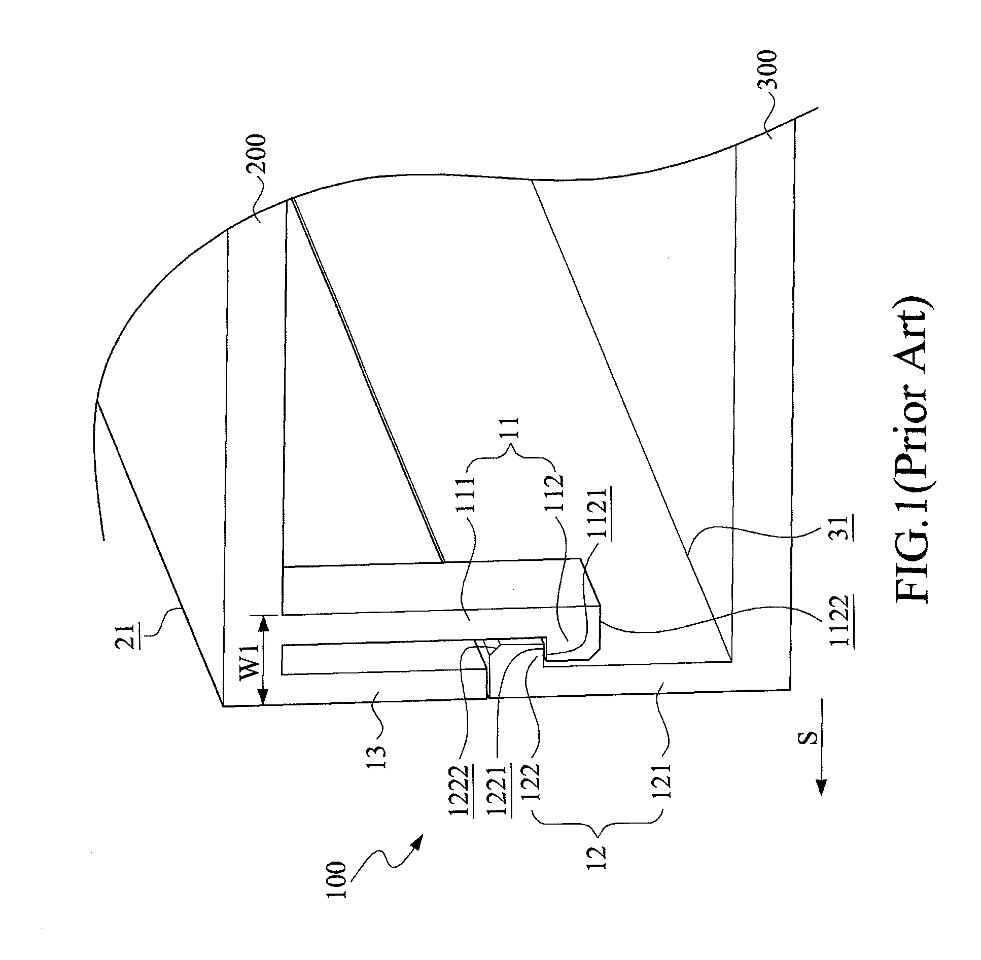
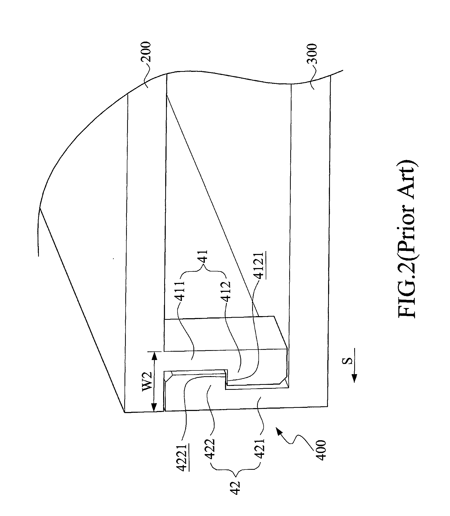
[0001]This application claims the benefits of the Taiwan Patent Application Serial NO. 099110531, filed on Apr. 6, 2010, the subject matter of which is incorporated herein by reference.BACKGROUND OF THE INVENTION[0002]1. Field of the Invention[0003]The present invention relates to a coupling structure, more particularly to a coupling structure for coupling first and second shell halves in order to form a shell or shell body.[0004]2. Description of the Prior Art[0005]Due to rapid advance in the electronic technology and due to habits of the electronic users, it is in the trend to minimize the dimension of the electronic devices. In many sophisticated electronics field, even a target to reduce a single centimeter in size is a challenging issue for the circuit design engineer. Therefore, to alter the product design of a shell to increase an internal circuit receiving space, undoubtedly permits flexible use of the circuit receiving space.[0006]Referring to FIG. 1, one embodiment of a co...

Claims


Application Information

Patent Timeline
IPC IPC(8): A44B13/00
CPCF16B5/065Y10T24/45236H05K5/0013F16B5/0664
Inventor HUANG, CHUN-TAO
Owner GIGA BYTE TECH CO LTD
Learn More