Sheet feeding apparatus and image forming apparatus

a technology of feeding apparatus and sensor arm, which is applied in the direction of transportation and packaging, thin material processing, and article separation, etc., can solve the problems of noise (impulsive sound), loud impulsive sound, and interference between sheet stacking plate and sensor arm

Inactive Publication Date: 2011-10-06
CANON KK
View PDF3 Cites 10 Cited by
  • Summary
  • Abstract
  • Description
  • Claims
  • Application Information

AI Technical Summary

Benefits of technology

[0018]The present invention provides a sheet feeding apparatus comprising, a sheet accommodating portion which can be brought into and out from an apparatus body, a sheet stacking portion, provided on the accommodating portion, on which is stacked sheets, a lift mechanism which pushes up the sheet stacking portion to a range where uppermost one of the sheets stacked on the sheet stacking portion can be fed, a driving portion provided in the apparatus body, and a damper portion provided on the sheet accommodating portion, wherein the lift mechanism can be engaged with and disengaged from the driving portion, and if the engagement between the lift mechanism and the driving portion is released, the lift mechanism lowers the sheet stacking portion, the damper portion is engaged with the lift mechanism, and if the engagement between the lift mechanism and the driving portion is released, the damper portion exerts damper effect on the lift mechanism to reduce a lowering speed of the sheet stacking portion, and wherein the damper portion does not exert the damper effect on the lift mechanism until the sheet stacking portion is lowered by a predetermined amount after the engagement between the lift mechanism and the driving portion is released.

Problems solved by technology

When the sheet cassette is pulled out, support of a lift mechanism is released and the sheet stacking plate is lowered (drops) by its own weight, but noise (impulsive sound) is generated in some cases due to impact that results when the lift mechanism is lowered.
Especially when a large amount of sheets is stacked on the sheet stacking plate, a loud impulsive sound is generated.
At that time, if the sensor arm is inserted into the opening of the sheet stacking plate, there is an adverse possibility that the sheet stacking plate and the sensor arm interfere with each other when the sheet cassette is pulled out.
Therefore, according to the conventional apparatus, when the sheet cassette is pulled out, the lowering speed of the sheet stacking plate is set to be fast immediately after the sheet cassette is pulled out, but the lowering speed of the sheet stacking plate can be fast only when the number of sheets stacked on the sheet stacking plate is small, and when a large number of sheets are stacked, the above-described problem cannot be solved.
In such as case, if the sheet cassette is pulled out, and the sensor arm and the feeding roller rub against the uppermost sheet, there is the possibility of the roller surface being scarred or the sheet being damaged by the uppermost curled up stacked sheet.
For this reason, when the sheet cassette is pulled out, it is necessary to increase the lowering speed of the sheet stacking plate but according to the conventional configuration, the lowering speed of the sheet stacking plate can be increased only when the number of sheets stacked on the sheet stacking plate is small, and the above-described problem cannot be solved when a large amount of sheets are stacked.
That is, according to the conventional configuration using the chipped-tooth gear, the lowering speed of the sheet stacking portion cannot be changed midstream depending upon a position (amount of sheets) of the sheet stacking portion when the cassette is pulled out.
It is not possible to increase the speed immediately after the sheet stacking portion is lowered when the cassette is pulled out irrespective of the amount of sheets.
If a plurality of dampers or chipped-tooth gears are provided, the above-described problem can be solved, but this increases costs and the problem can be solved only in stages.

Method used


Image

  • Sheet feeding apparatus and image forming apparatus
  • Sheet feeding apparatus and image forming apparatus
  • Sheet feeding apparatus and image forming apparatus

Examples


Embodiment Construction

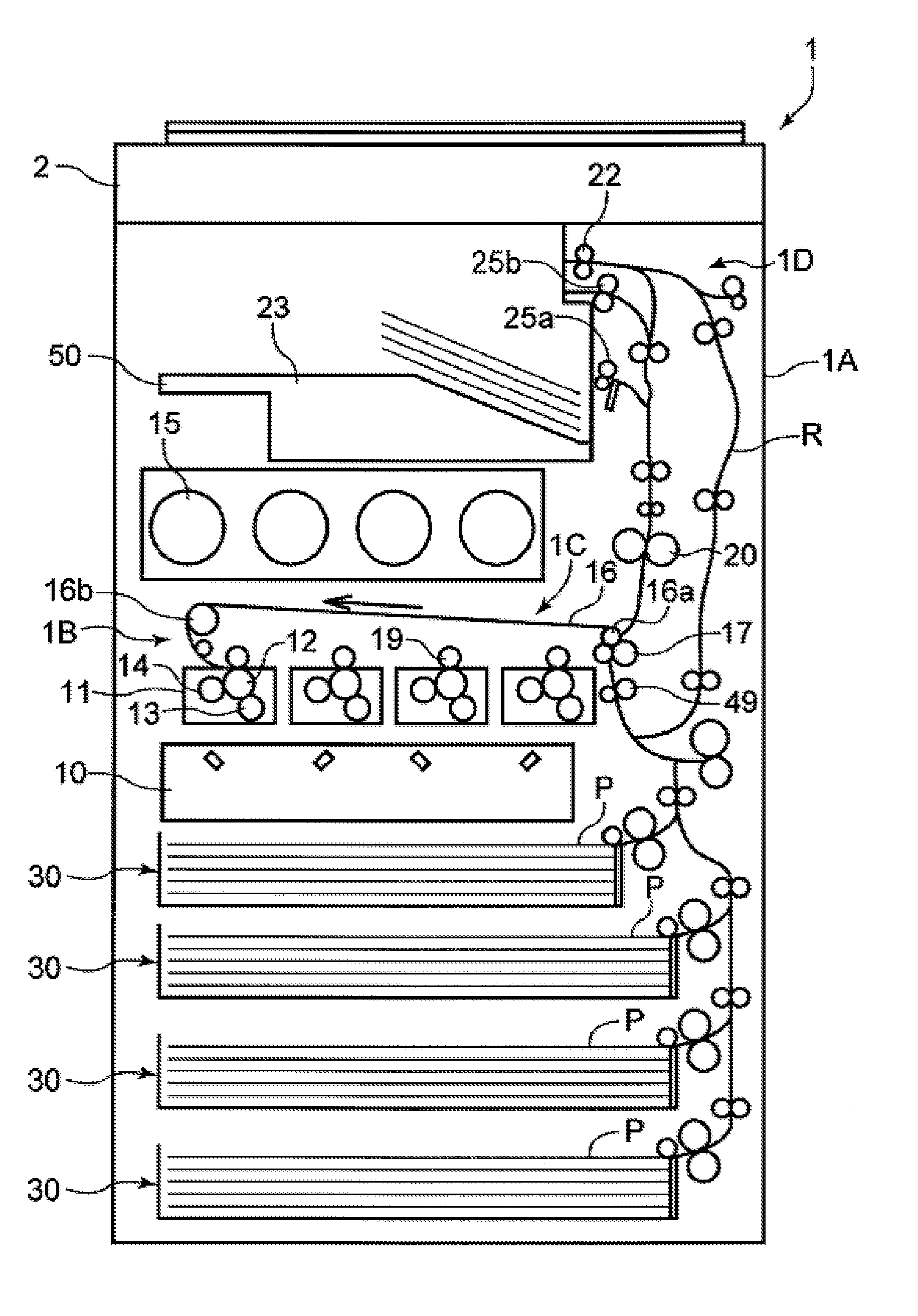
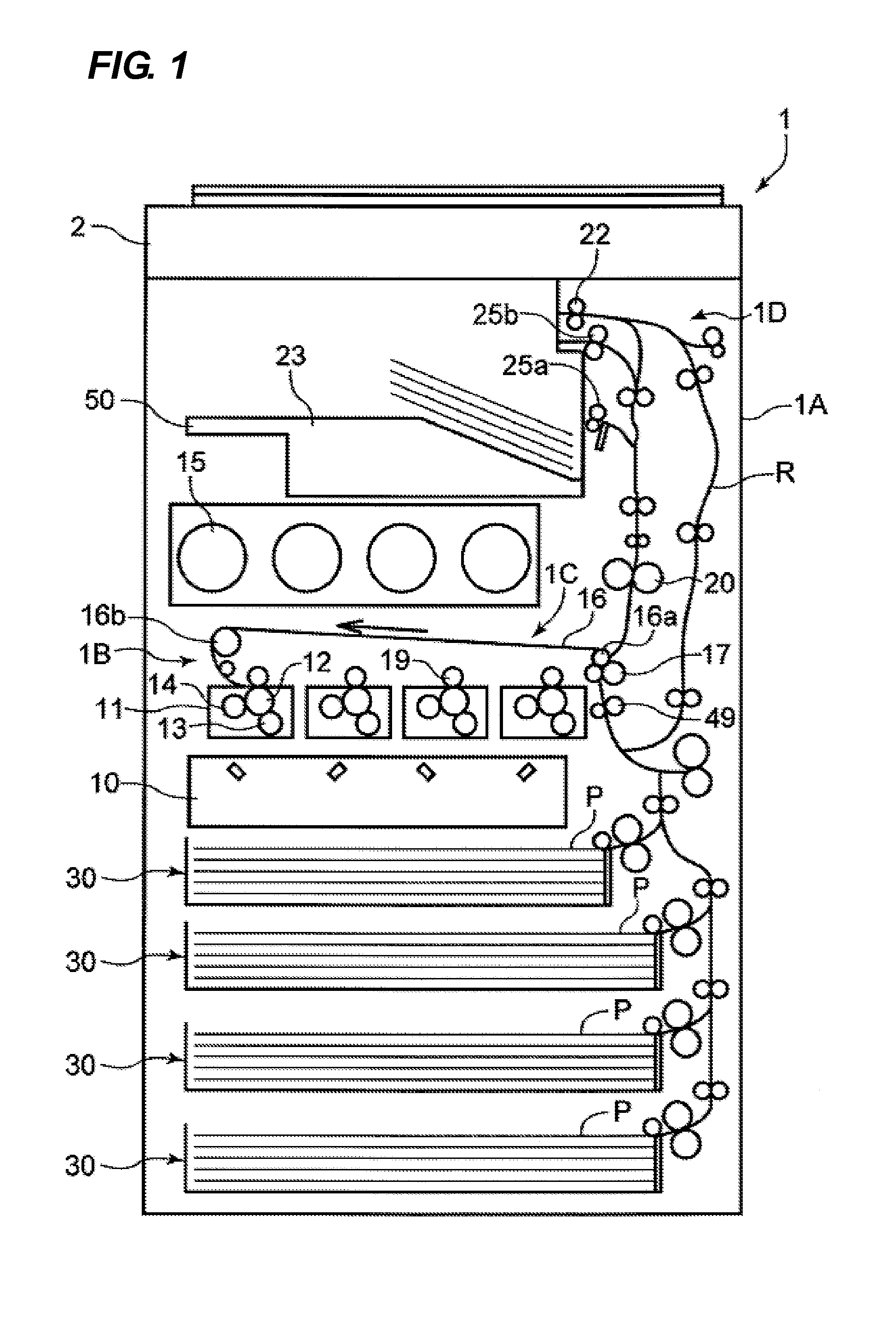
[0029]Embodiments of the present invention will be described in detail with reference to the drawings. FIG. 1 is a diagram illustrating a general configuration of a full-color laser beam printer which is one example of an image forming apparatus according to the embodiment of the invention.

[0030]In FIG. 1, a full-color laser beam printer 1 (printer, hereinafter) includes a printer body 1A which is an image forming apparatus body, an image forming portion 1B which forms an image on a sheet, and a fixing portion 20. An image reading apparatus 2 is an upper portion apparatus disposed substantially horizontally above the printer body 1A, and a sheet discharge space S into which a sheet is discharged is formed between the image reading apparatus 2 and the printer body 1A. The full-color laser beam printer includes a sheet feeding apparatus 30 provided in a lower portion of the printer body 1A, and a toner cartridge 15.

[0031]The image forming portion 1B is a drum full-color image forming ...


PUM


Abstract

A sheet feeding apparatus has a sheet accommodating portion, a sheet stacking portion, a lift mechanism, a driving portion provided, and a damper portion. The lift mechanism can be engaged with and disengaged from the driving portion, and if the engagement between the lift mechanism and the driving portion is released, the lift mechanism lowers the sheet stacking portion, the damper portion is engaged with the lift mechanism, and if the engagement between the lift mechanism and the driving portion is released, the damper portion exerts damper effect on the lift mechanism to reduce a lowering speed of the sheet stacking portion, and wherein the damper portion does not exert the damper effect on the lift mechanism until the sheet stacking portion is lowered by a predetermined amount after the engagement between the lift mechanism and the driving portion is released.

Description

[0001]This application claims the benefit of Japanese Patent Application No. 2010-086464, filed Apr. 2, 2010, which is hereby incorporated by reference herein in its entirety.BACKGROUND OF THE INVENTION[0002]1. Field of the Invention[0003]present invention relates to a sheet feeding apparatus and an image forming apparatus, and more particularly, to control of a lowering speed when a sheet stacking plate on which sheets are stacked is lowered.[0004]2. Description of the Related Art[0005]A conventional image forming apparatus such as a printer, a facsimile machine or a copying machine is provided with a sheet feeding apparatus which separates an uppermost one of a plurality of sheets accommodated in a sheet cassette and feeds the separated sheet. The sheet feeding apparatus has a sheet cassette and a sheet stacking plate provided in the sheet cassette such that the sheet stacking plate can be lifted and lowered, and sheets are stacked and supported on the sheet stacking plate. When a...

Claims


Application Information

Patent Timeline
Patent Type & Authority Applications(United States)
IPC IPC(8): B65H1/08
CPCB65H1/14B65H1/266B65H2601/521B65H2403/60B65H2403/421
Inventor SEKIGUCHI, HAJIME
Owner CANON KK
Why Eureka
Try Eureka