Current Mode Buck Converter with Fixed PWM/PFM Boundary

a current mode and boundary technology, applied in the direction of electric variable regulation, process and machine control, instruments, etc., can solve the problems of small current threshold ith and inaccessibility of pfm mod

Inactive Publication Date: 2011-10-06
ANPEC ELECTRONICS CORPORATION
View PDF0 Cites 72 Cited by
  • Summary
  • Abstract
  • Description
  • Claims
  • Application Information

AI Technical Summary

Benefits of technology

[0010]The present invention discloses a current mode buck converter, which comprises an input end for receiving an input voltage, an output end for outputting an output voltage, a feedback module coupled to the output end for generating a feedback signal according to the output voltage, a switch module for determining whether the input end is electrically connected to a ground end according to a switch signal, an output module comprising an output inductor coupled between the switch module and the output end, an output resistor coupled to the output end, and an output capacitor coupled between the output resistor and the ground end, a current sensor coupled between the switch module and the output module for detecting an inductor current of the output inductor to generate a sensing current, a current sense circuit coupled to the current sensor for amplifying the sensing current to recover the inductor current for generating a first mirror inductor current and a second mirror inductor current, a slope compensation circuit coupled to the current sense circuit for generating a first slope compensation current and a second slope compensation current, a first resistor coupled to the current sense circuit and the slope compensation circuit for converting a sum of the first mirror inductor current and the first slope compensation current into a sensing voltage, an error amplifier coupled to the feedback module for amplifying a difference between the feedback signal and a first reference signal to generate a differential voltage, a pulse width modulation (PWM) compensation circuit coupled to the error amplifier for compensating a frequency response of the buck converter according to the differential voltage to generate a compensation result, a first comparator coupled to the current sense circuit the slope compensation circuit, the first resistor and the PWM compensation circuit for comparing the sensing voltage and the compensation result to generate a PWM signal, a second comparator coupled to the feedback module for comparing the feedback signal and a divided voltage of the first reference voltage to generate a PWM trigger signal, a third comparator for comparing a second reference voltage and a threshold voltage to generate a pulse frequency modulation (PFM) trigger signal, an oscillator for generating an oscillating signal, and a modulation control circuit coupled to the first comparator, the second comparator, the third comparator and the oscillator for generating the switch signal sent to the switch module according to the PWM trigger signal, the PFM trigger signal, the PWM signal and the oscillating signal.

Problems solved by technology

However, the threshold voltage adjustment probably results in a very small current threshold Ith1, implying that the PFM mode is inaccessible.

Method used


Image

  • Current Mode Buck Converter with Fixed PWM/PFM Boundary
  • Current Mode Buck Converter with Fixed PWM/PFM Boundary
  • Current Mode Buck Converter with Fixed PWM/PFM Boundary

Examples


Embodiment Construction

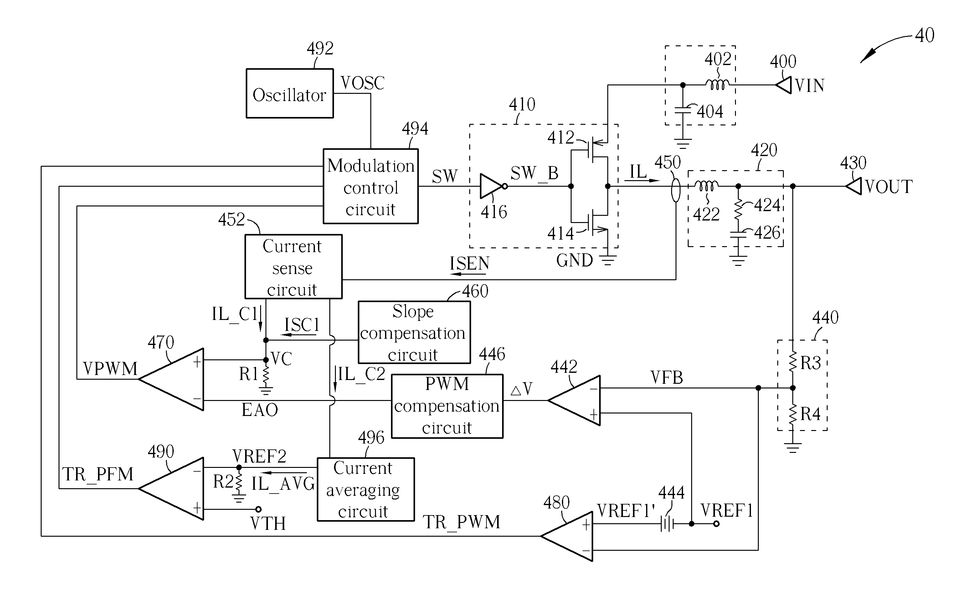
[0019]Please refer to FIG. 4A, which is a schematic diagram of a current mode buck converter 40 according to an embodiment of the present invention. The buck converter 40 includes an input end 400, an output end 430, a feedback module 440, a switch module 410, an output module 420, a current sensor 450, a current sense circuit 452, a slope compensation circuit 460, a first resistor R1, a second resistor R2, an error amplifier 442, a pulse width modulation (PWM) compensation circuit 446, a first comparator 470, a second comparator 480, a third comparator 490, an oscillator 492, a modulation control circuit 494, an input inductor 402, an input capacitor 404, an voltage reduction circuit 444 and a current averaging circuit 496. The input end 400 is utilized for receiving an input voltage VIN. The input inductor 402 and the input capacitor 404 are utilized for performing low-pass filtering on the input voltage VIN. The switch module 410 is utilized for determining whether the input end ...


PUM


Abstract

A current mode buck converter is disclosed. The buck converter operates in a pulse width modulation (PWM) mode or a pulse frequency modulation (PFM) mode. To prevent an output inductor with various probable magnitudes from varying a decision boundary between the PWM mode and the PFM mode, the buck converter adaptively adjusts a triggering condition for the pulse frequency modulation mode according to an average value of an inductor current of the output inductor or AC components of the inductor current and a slope compensation current.

Description

BACKGROUND OF THE INVENTION[0001]1. Field of the Invention[0002]The present invention is related to a current mode buck converter, and more particularly, to a current mode buck converter adaptively adjusting a trigger condition for a pulse frequency modulation mode according to an average of an inductor current or AC components of the inductor current and a slope compensation current, to prevent variations of an input voltage, an output voltage and the inductor current.[0003]2. Description of the Prior Art[0004]An electronic device generally includes various components requiring different operating voltages. Therefore, a DC-DC voltage converter is essential for the electronic device to adjust (step up or step down) and stabilize voltage levels. Based upon different power requirements, various types of DC-DC voltage converter, originating from a buck (step down) converter and a boost (step up) converter, are developed. Accordingly, the buck converter can decrease an input DC voltage ...

Claims


Application Information

Patent Timeline
Patent Type & Authority Applications(United States)
IPC IPC(8): G05F1/10
CPCH02M3/1588Y02B70/1466H02M2001/0025Y02B70/10H02M1/0025
Inventor CHEN, CHIH-NINGSHENG, KANG
Owner ANPEC ELECTRONICS CORPORATION
Why Eureka
Try Eureka