Tightly coupled iron core set and winding rack

a technology of iron cores and winding racks, which is applied in the direction of transformers/inductance coils/windings/connections, transformer/inductance details, electrical equipment, etc., can solve the problems of transformer disintegration, high cost, and high cost, and achieve the effect of maintaining a reasonable level of cost and loosing easily

Inactive Publication Date: 2011-10-06
INNOTRANS TECH
View PDF0 Cites 14 Cited by
  • Summary
  • Abstract
  • Description
  • Claims
  • Application Information

AI Technical Summary

Benefits of technology

[0005]In view of the aforesaid conventional assembling techniques still cannot achieve a desirable balance between production yield and cost, the primary object of the present invention is to provide...

Problems solved by technology

However, the winding rack has a large area exposed outside the iron cores, hence still has room for improvement in terms of magnetic leakage and EMI.
The aforesaid conventional transformer, aside from the problem of magnetic leakage needed to be improved, the coupling of the upper and lower iron cores also creates other problem needed to...

Method used


Image

  • Tightly coupled iron core set and winding rack
  • Tightly coupled iron core set and winding rack
  • Tightly coupled iron core set and winding rack

Examples


Embodiment Construction

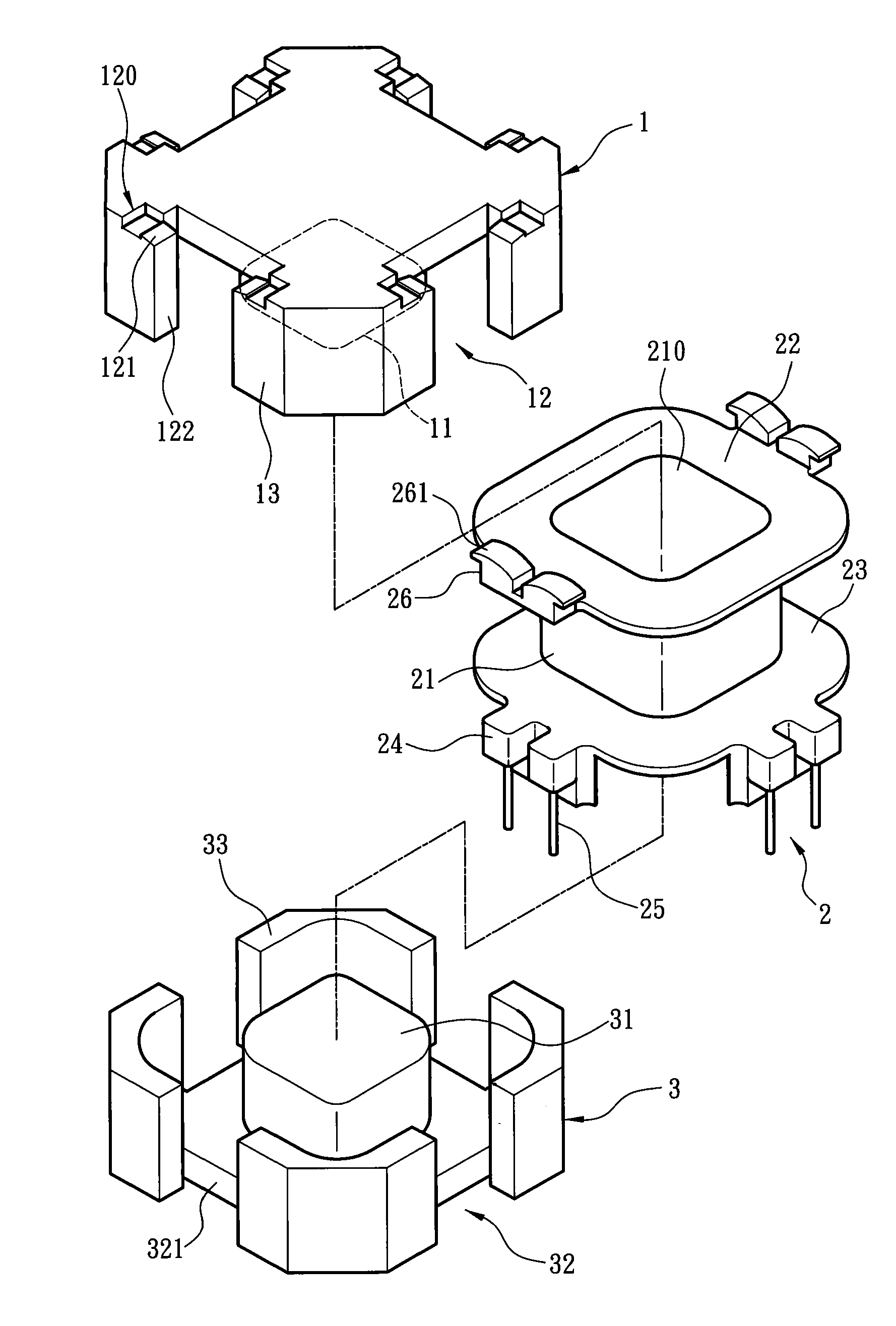
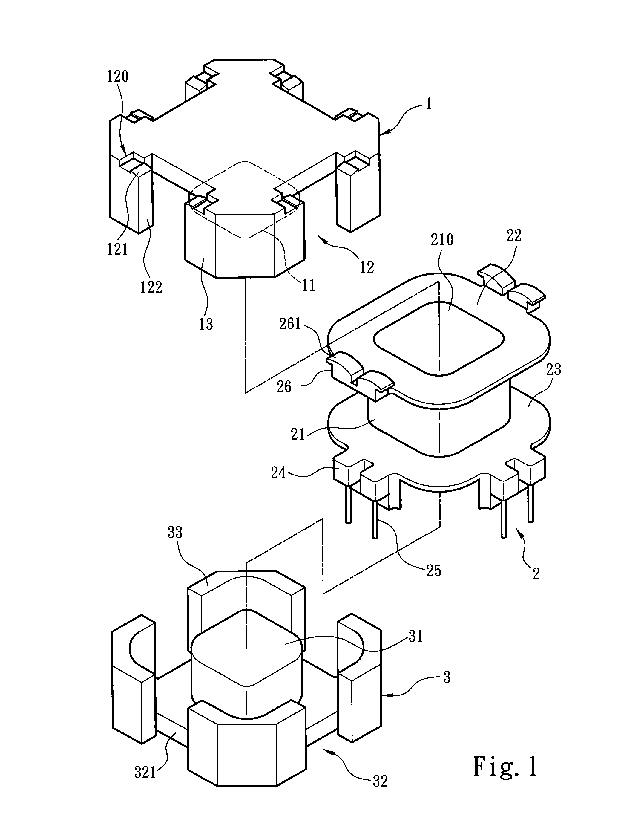
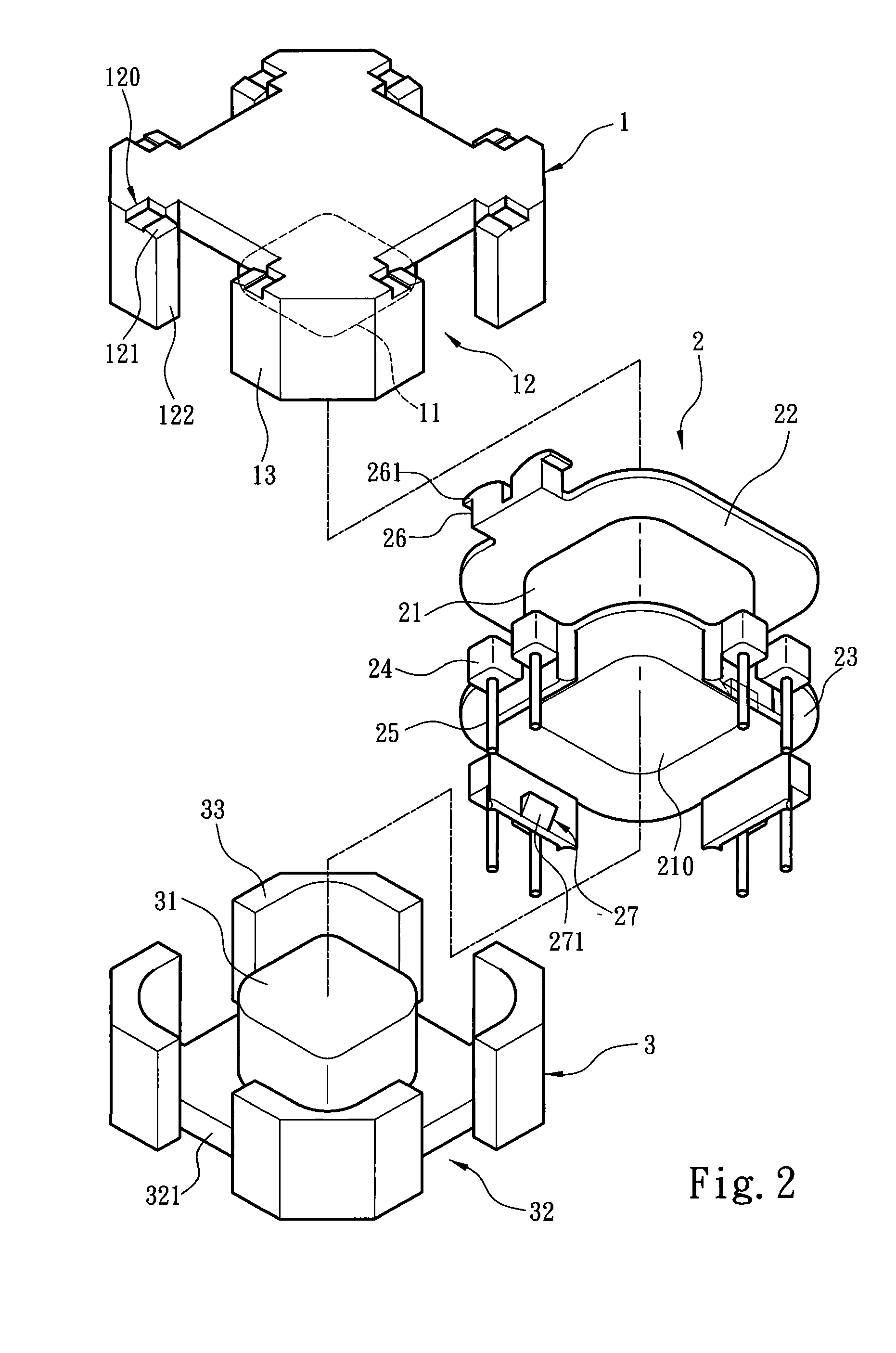
[0021]The present invention aims to provide tightly coupled iron core set and winding rack. Please refer to FIGS. 1 and 2 for a first embodiment of the invention. A winding rack 2 and an iron core set are provided. The iron core set includes a first iron core 1 and a second iron core 3. The winding rack 2 includes a hollow bobbin 21, a first partition board 22 and a second partition board 23. The bobbin 21 has two ends respectively with an opening 210. The first and second partition boards 22 and 23 are extended respectively and radially from the opening 210, and spaced from each other to form an area for winding. The second partition board 23 has a plurality of pin sections 24 connected to a plurality of conductive pins 25. A winding wound on the bobbin 21 can be electrically connected with the pins 25 through the pin sections 24. It is to be noted that while the pin sections 24 are located on the second partition board 23 in this embodiment, in practice the pin sections 24 may als...


PUM


Abstract

A tightly coupled iron core set and winding rack structure includes a winding rack and an iron core set. The winding rack includes a hollow bobbin, a first partition board and a second partition board extended radially from openings at two ends of the bobbin, and a plurality of pin sections located on the second partition board. The first and second partition boards have respectively at least one latch portion. The iron core set includes a core running through the bobbin and a plurality of latch notches coupled with the latch portions to hold the iron core set on the winding rack. Thus the iron core set can be directly latched on the winding rack to form coupling without using extra bonding or latching tools.

Description

FIELD OF THE INVENTION[0001]The present invention relates to tightly coupled iron core set and winding rack and particularly to a self-fastening structure to easily couple an iron core set and a winding rack without using any auxiliary tools.BACKGROUND OF THE INVENTION[0002]A conventional transformer or filter generally is formed by coupling at least one winding rack and at least one iron core to perform electromagnetic conversion to achieve its designed objective. To meet such a purpose (take the transformer as an example), the iron core and winding rack can be formed in various types to provide different functions. In order to improve electromagnetic interference (EMI), some transformers or filters adopt an EE-type iron core or EI-type iron core to encase the winding rack. For instance, R.O.C. patent No. 592377 entitled “Improved transformer structure” discloses a transformer comprising an upper iron core, a lower iron core, a plastic holder, a circuit board, a Mylar insulation fi...

Claims


Application Information

Patent Timeline
IPC IPC(8): H01F27/30
CPCH01F27/306
Inventor LU, WEN-CHING
Owner INNOTRANS TECH
Why Eureka
Try Eureka