Planar transformer and method of manufacturing the same

a technology of transformers and transformers, applied in the direction of transformers/inductance coils/windings/connections, magnets, etc., can solve the problems of deterioration of insulating performance, inability to reduce the size of capacitors, and inability to meet the requirements of the size of the transformer

Inactive Publication Date: 2011-10-06
SOLUM CO LTD
View PDF14 Cites 17 Cited by
  • Summary
  • Abstract
  • Description
  • Claims
  • Application Information

AI Technical Summary

Benefits of technology

[0011]An aspect of the present invention provides a planar transformer and a method of manufacturing the same that can prevent resin being coated during the manufacturing of a transformer from being separated from a conductor by forming a dummy pattern on a board.

Problems solved by technology

However, size reduction may be inhibited by magnetic devices and capacitors.
However, while the boards are being stacked upon one another, the resins being injected may detach between patterns, where insulation is required, which may lead to a deterioration in insulating performance.

Method used


Image

  • Planar transformer and method of manufacturing the same
  • Planar transformer and method of manufacturing the same
  • Planar transformer and method of manufacturing the same

Examples


Embodiment Construction

[0035]Exemplary embodiments of the present invention will now be described in detail with reference to the accompanying drawings.

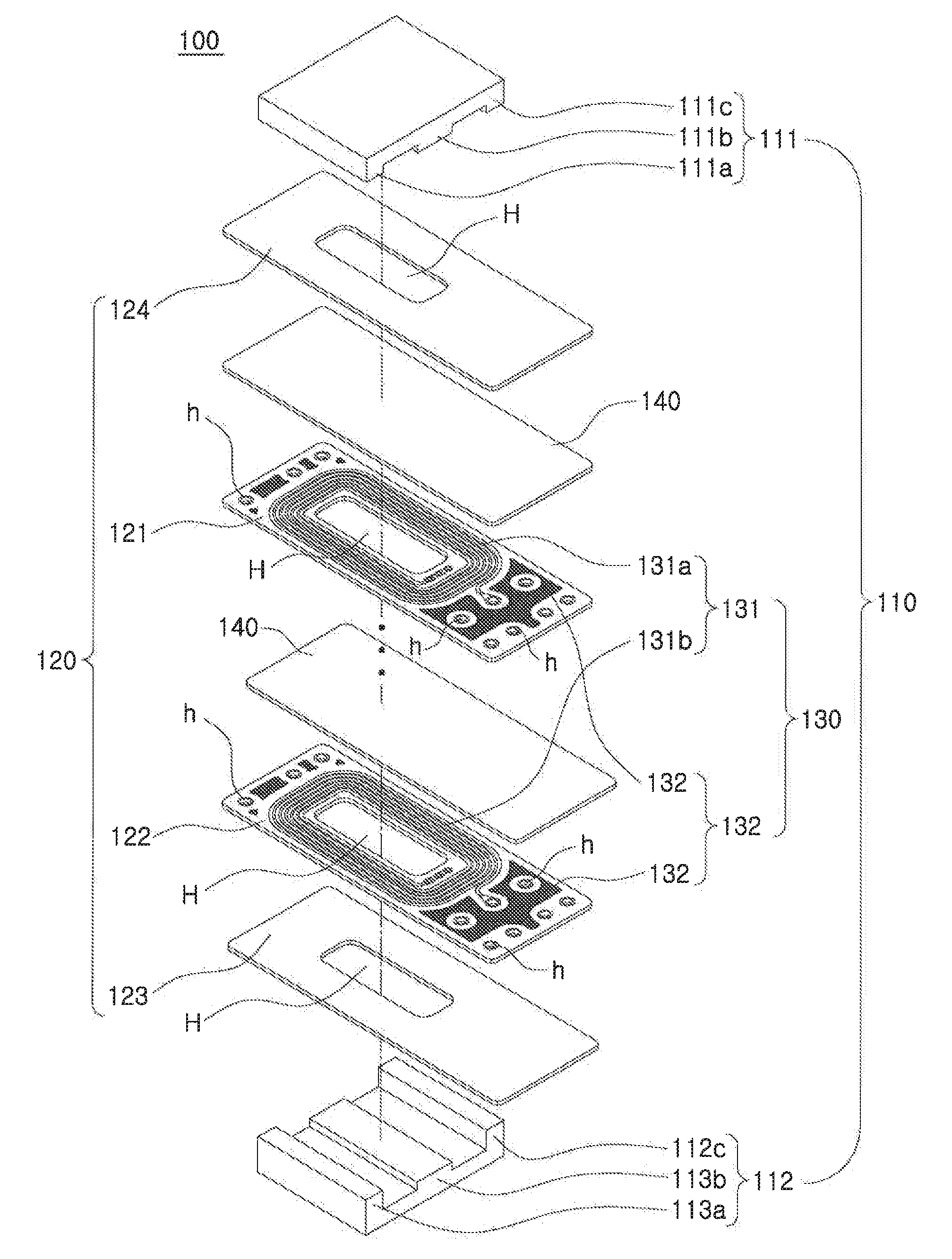
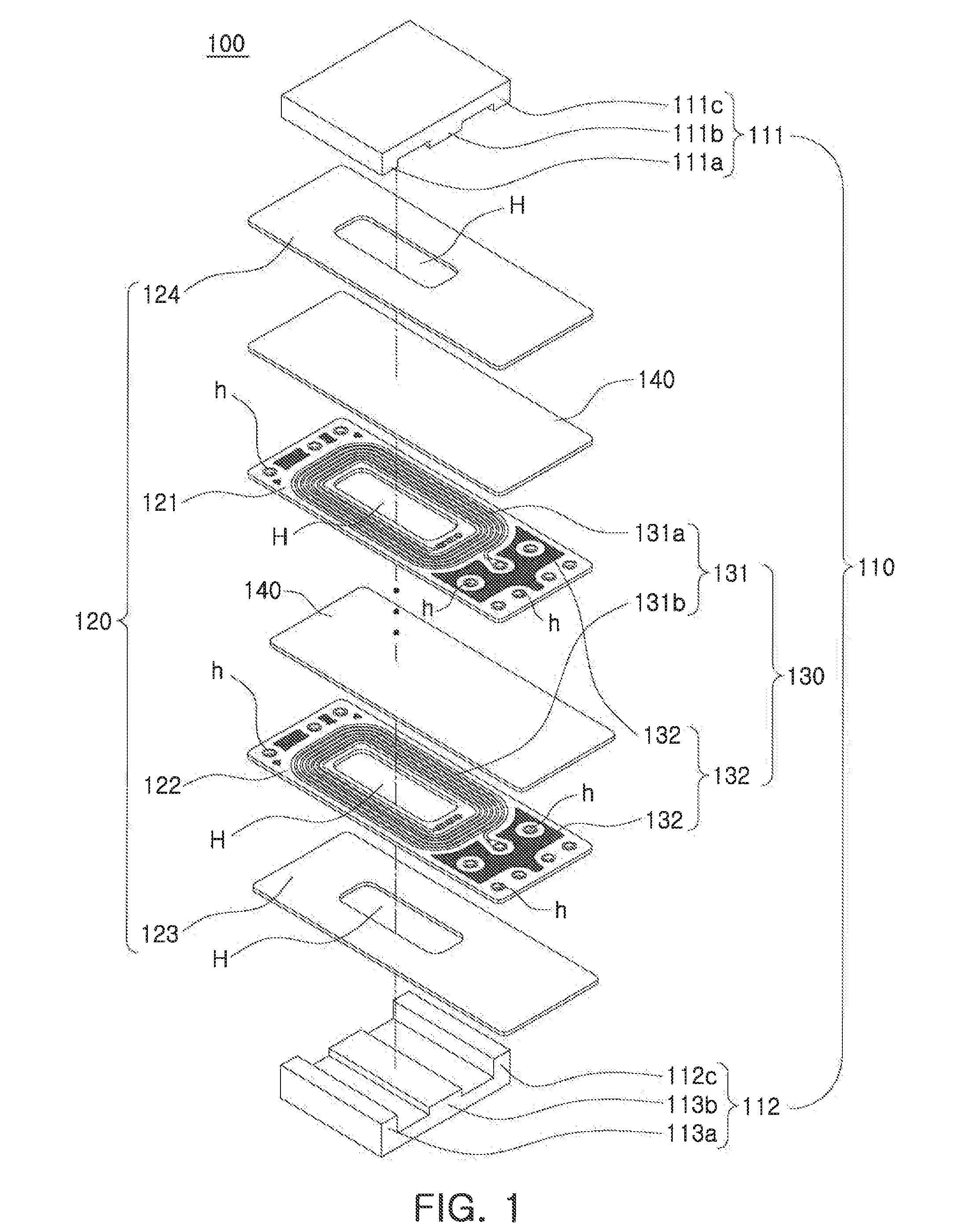
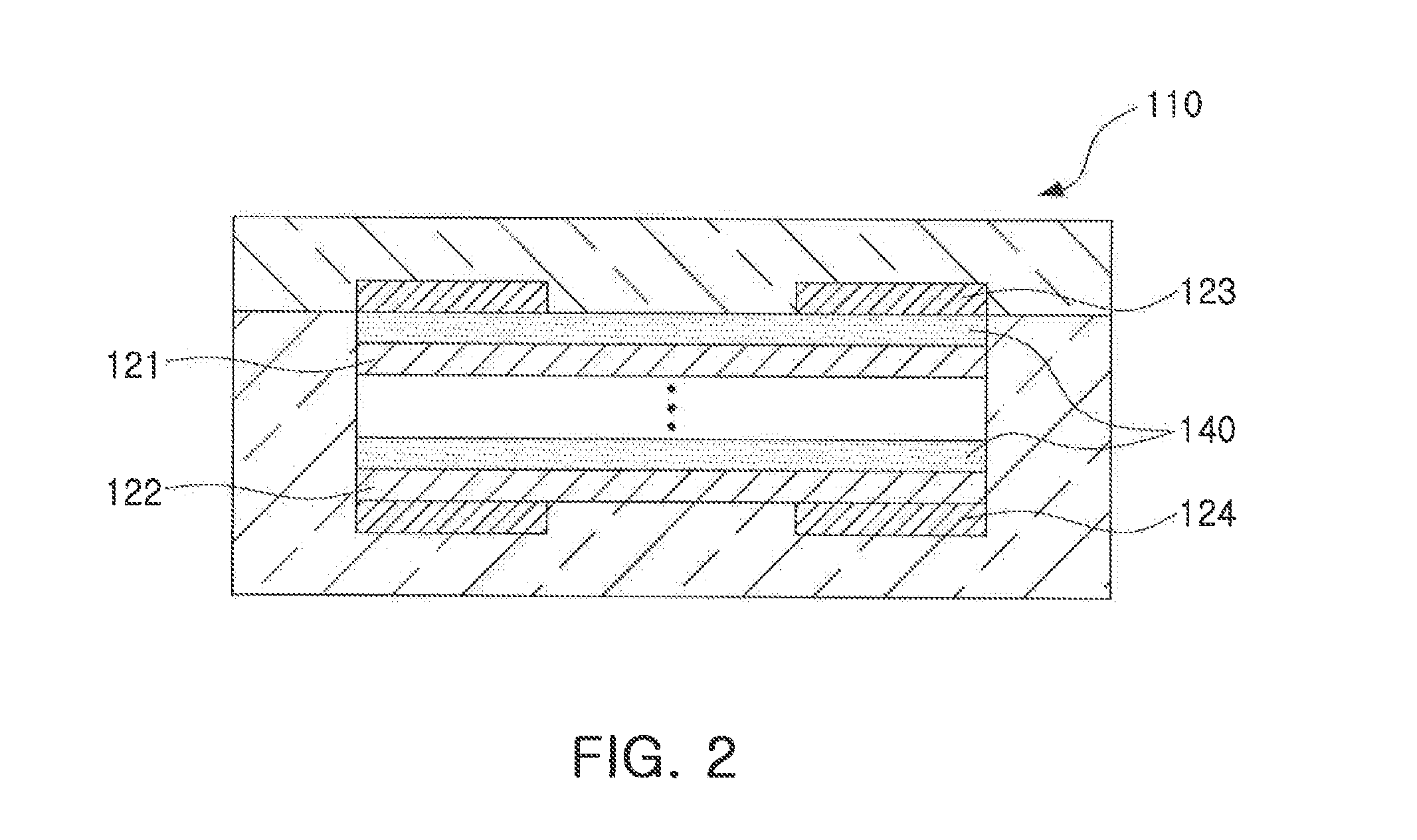
[0036]FIG. 1 is a schematic exploded perspective view illustrating a transformer according to an exemplary embodiment of the invention. FIG. 2 is a schematic side view illustrating a transformer according to an exemplary embodiment of the invention.

[0037]Referring to FIG. 1, a planar transformer 100 according to this embodiment may include a core part 110, a board part 120, and a pattern part 130.

[0038]The core part 110 may include a pair of cores 111 and 112 that are electromagnetically coupled to each other.

[0039]The pair of cores 111 and 112 may include respective legs that are electromagnetically coupled to each other.

[0040]As described in FIG. 1, the pair of cores 111 and 112 may be EE cores. However, the present invention is not limited thereto, and the pair of cores 111 and 112 may be EI cores, UU cores, UI cores, and the like.

[0041]As described in ...


PUM

PropertyMeasurementUnit
power transmissionaaaaaaaaaa
circumferenceaaaaaaaaaa
transmitting poweraaaaaaaaaa

Abstract

There are is a planar transformer and a method of manufacturing the same that can prevent resin being coated from being separated from a conductor during the manufacturing of a transformer by forming a dummy pattern on a board. A planar transformer according to an aspect of the invention may include: a core part having a pair of cores electromagneticaliy coupled to each other; a board part having a plurality of boards disposed between the pair of cores and stacked upon one another; a pattern part having a power transmission pattern provided on at least one board of the plurality of boards of the board part and transmitting power being input, and a dummy pattern provided on the same board having the power transmission pattern thereon and separated from the power transmission pattern by a predetermined interval; and a resin part being coated over the at least one board of the plurality of boards, the at least one board having the pattern part thereon.

Description

CROSS-REFERENCE TO RELATED APPLICATIONS[0001]This application claims the priority of Korean Patent Application No. 10-2010-0031027 tiled on Apr. 5, 2010, in the Korean Intellectual Property Office, the disclosure of which is incorporated herein by reference.BACKGROUND OF THE INVENTION[0002]1. Field of the Invention[0003]The present invention relates to a planar transformer and a method of manufacturing the same, and more particularly, to a planar transformer and a method of manufacturing one same that can prevent resin, being coated, from being separated from a conductor during the manufacturing of a transformer by forming a dummy pattern on a board.[0004]2. Description of the Related Art[0005]With the trend toward the size reduction of various kinds of electronic apparatuses, there is also a need for the size reduction of power supply units.[0006]Basically, the size reduction of power supplies can be achieved by driving power terminals with a high frequency. However, size reduction...

Claims


Application Information

Patent Timeline
Patent Type & Authority Applications(United States)
IPC IPC(8): H01F27/28H01F7/06
CPCH01F27/2804H01F2027/2809Y10T29/4902H01F41/34H01F2027/2819
Inventor PARK, GEUN YOUNGSEO, SANG JOONJUNG, JIN ANCHO, KWANG SEUNGKIM, DEUK HOON
Owner SOLUM CO LTD
Why Eureka
Try Eureka