Fishing reel

Inactive Publication Date: 2005-05-24
DAIWA SEIKO CORPORATION
View PDF19 Cites 14 Cited by
  • Summary
  • Abstract
  • Description
  • Claims
  • Application Information

AI Technical Summary

Benefits of technology

[0015]In view of the above mentioned shortcomings, it is objects of the invention to offer such a fishing reel of improved endurance by using a core wired belt for serving the drive force transmitting mechanism constitut

Problems solved by technology

However, in cases of structures of Patent Laid Open No. 32632/1999 and No. 8590/2001, since the power transmission is performed by driving the belt in parts not effected with load, troubles are less to occur, but in case the disclosed fishing reels are used in parts transmitting a large power, the belt has difficulty about endurance, and such a trouble might occur where the belt is broken due to work for a long duration.
If the grease is blown off from the tooth flank, the tooth flank is effected with intensive abrasion or much corrosion by a seawater.
Thus, a limitation exists in making the reel compact.
Further, being many number of gears, noises or vibrations are large, so that there are inconveniences that a grip and holding property of the reel is inferior, and no concentration can be made on fishing, and so the earlier improvement is required.
Problems of the related art are that if the pulleys and the belt are used for transmitting a power in the drive mechanism of the fishing reel, difficult

Method used


Image

  • Fishing reel
  • Fishing reel
  • Fishing reel

Examples


Example

First Embodiment

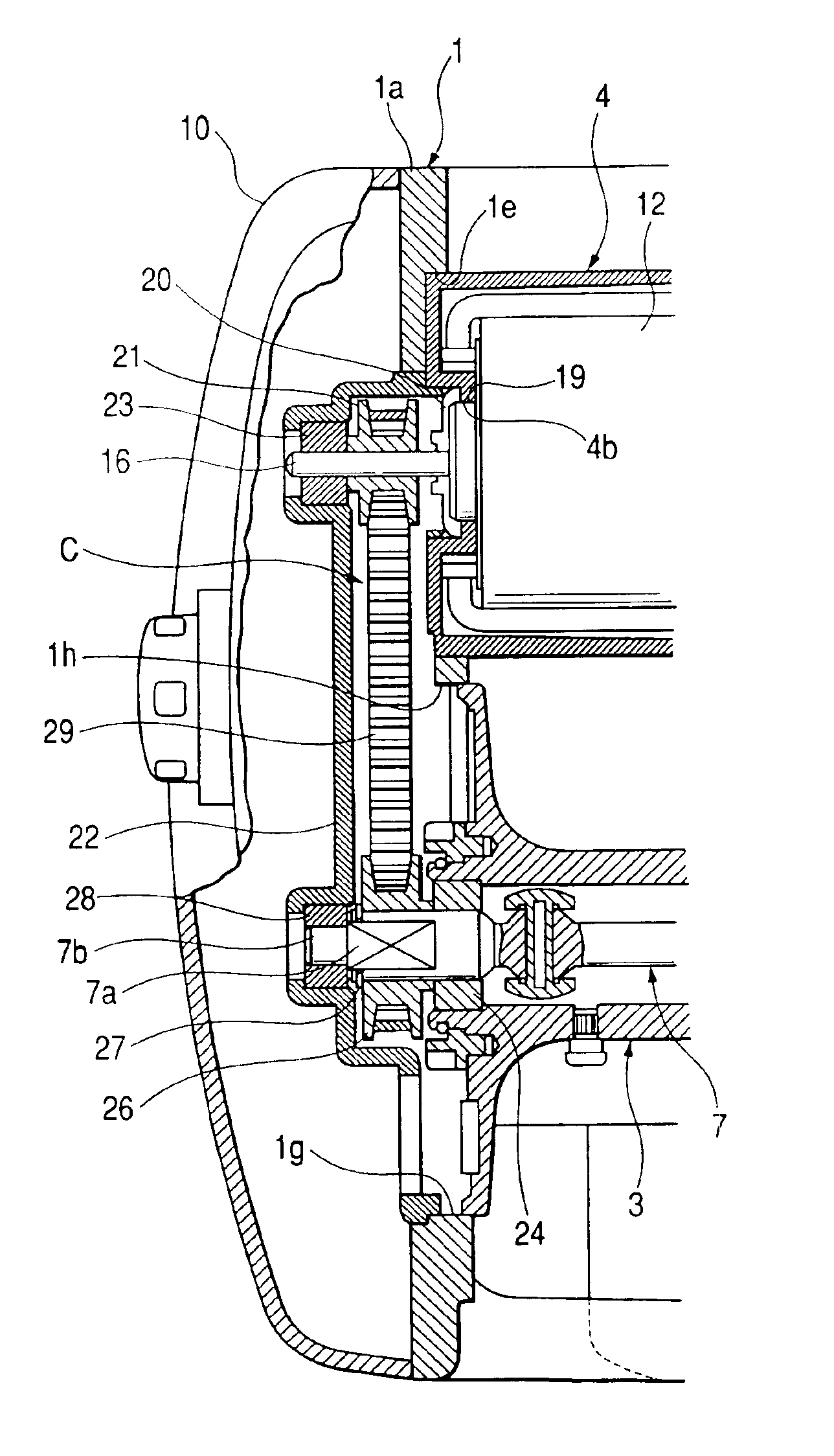
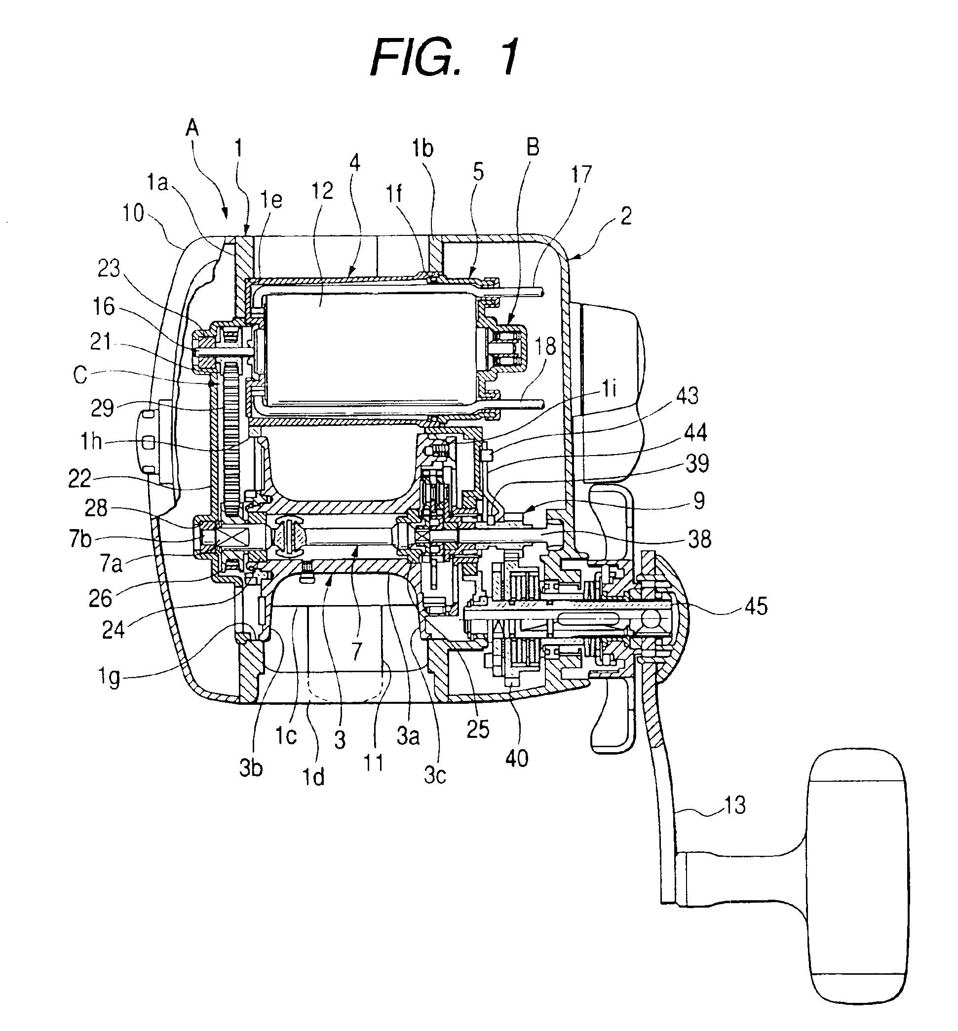
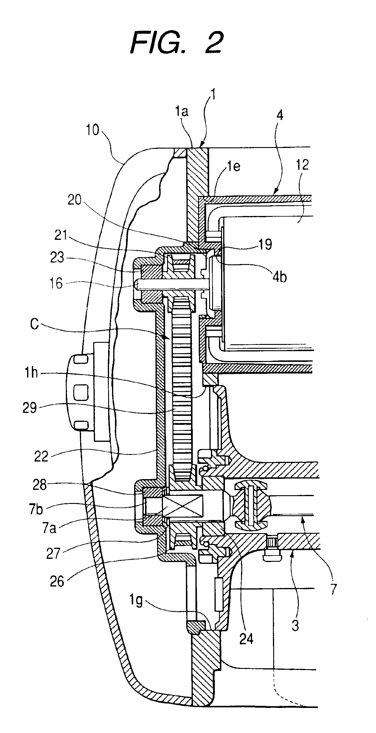
[0044]The invention will be explained with reference to an embodiment shown in the attached drawings. FIGS. 1 through 8 are a first embodiment. FIG. 1 is a cross sectional side view of the electric reel, FIG. 2 is an enlarged cross sectional side view opposite to a handle side of the electric reel, FIG. 3 is an enlarged cross sectional side view of the handle side of the electric reel, FIG. 4 is an enlarged cross sectional plan view, FIG. 5 is a side view of an inside of a side panel opposite to the handle of the electric reel, FIG. 6 is an enlarged cross sectional side view of toothed pulleys and a toothed belt, FIG. 7 is a side view opposite to the handle of the electric reel, and FIG. 8 is a side view of the inside of the side panel of the handle side of the electric reel.

[0045]The reel main body A of the electric fishing reel comprises a frame 1 and a side plates 10, 2.

[0046]The frame 1 includes right and left side frames 1a and 1b, a support (not shown), a stati...

Example

Second Embodiment

[0106]FIG. 9 is a second embodiment showing a cross sectional perspective view.

[0107]The second embodiment is a modified example of the toothed belt 29 according to the first embodiment. A toothed belt 129 according to the second embodiment is constituted by a rubber 129a and core wires 129b. The rubber 129a is formed with a material such as chloroprene rubber or polyurethane. The core wires 129b is made of glass fiber or aramid fiber having larger tensile strength than that of a belt base material and is provided at the interior of the rubber 129a of a toothed belt 129. Other structures are the same as those of the first embodiment, and explanation will be omitted.

[0108]By forming the core wired toothed belt 129 as mentioned above, the belt is less to be elongated so that pitches of the belt teeth and length of the belt are kept proper, and the toothed pulleys 21, 26 are correctly in mesh with the toothed belt 129, and flat-abrasion in belt teeth is solved and endu...

Example

Third Embodiment

[0109]FIGS. 10 to 12 show a third embodiment. FIG. 10 is an enlarged cross sectional side view, FIG. 11 is a cross sectional side view along H—H of FIG. 10, and FIG. 12 is perspective views of the pulley and the belt of FIG. 10.

[0110]The third embodiment is modified examples of the toothed pulleys 21, 26 and the core wired toothed belt 129 according to the second embodiment, in which pulleys 21a, 26a where the teeth are removed from the toothed pulleys 21, 26 and a belt 229 where the teeth 129 are removed from the core wired toothed belt 129 are employed. Other structures are the same as those of the first and second embodiments, and explanation will be omitted.

[0111]By using the core wired belt 229 as mentioned above, strength and endurance are increased, and belts of narrow width may be employed. There is no insufficient contacting pressure between the belt 229 and the pulleys 21a, 26a owing to elongation of the belt 229, so that failure of the power transmission i...


PUM


Abstract

A belt and pulleys are used as a power transmitting unit in a fishing reel for avoiding uncomfortable vibration or noises while fishing. A spool motor is supported in a motor receiving case provided at front and lower parts between both side frames, and a toothed pulley 21 is urged in the other side of a rotating shaft and is made detent. Another toothed pulley is fitted in a detent portion of a spool shaft by an E-ring, and a toothed belt is expanded between the toothed pulley and the other toothed pulley.

Description

BACKGROUND OF THE INVENTION[0001]This invention relates to a fishing reel in which a power transmission instrument of a drive mechanism for driving composing parts provided within a reel main body is improved.[0002]In a related art, the fishing reel supports, within the reel main body, a drive mechanism for winding a fishing line on a spool held by the reel main body and a fishing line parallel winding mechanism for winding the fishing line in parallel on the spool.[0003]The drive mechanisms generally carry out power transmission through a gear train between a plurality of separate drive shafts. For purposes of reducing noises of the gears in the fishing reel, heightening precision, lightening weight, and making compact, Patent Laid Open No. 32632 / 1999 and No. 8590 / 2001 disclose fishing reels with pulleys and belts.[0004]However, in cases of structures of Patent Laid Open No. 32632 / 1999 and No. 8590 / 2001, since the power transmission is performed by driving the belt in parts not eff...

Claims


Application Information

Patent Timeline
IPC IPC(8): A01K89/017A01K89/00
CPCA01K89/017A01K89/0183
Inventor CHIBA, MAKOTO
Owner DAIWA SEIKO CORPORATION
Why Eureka
Try Eureka