Method for Detecting Small Targets in Radar Images Using Needle Based Hypotheses Verification

a technology of radar images and hypotheses, applied in the field of radar image detection, can solve the problems of increasing the cost of false alarms, noise, electromagnetic interference, etc., and avoiding the detection of small targets in noisy environments, so as to avoid the cost of increasing the number of false alarms

Inactive Publication Date: 2011-10-06
MITSUBISHI ELECTRIC RES LAB INC
View PDF9 Cites 30 Cited by
  • Summary
  • Abstract
  • Description
  • Claims
  • Application Information

AI Technical Summary

Problems solved by technology

In addition to a potential target reflection signal, the image also includes noise, electromagnetic interference, and clutter.
It is extremely difficult to detect very small targets in noisy environments.
If the threshold is too low, then more targets are detected, at the expense of an increased numbers of false alarms.
However, for a lower SNR, where targets cannot be easily distinguished from the cluttered noisy background, such cell thresholding approaches give large rates of false detections.
Even for these small 21×21 cell images, the target signal cannot be easily identified.
In addition, cell responses with high intensities are only weakly correlated to the locations of the targets.
A discrete state space often leads to high computation and memory requirements.
Although the particle filtering can achieve similar estimation performance for lower cost by using fewer sampling points than are required for a discrete grid, particle filtering usually requires a considerable amount of particles to effectively approximate continuous probabilistic distributions.
Thus, the computational burden for high dimensional state spaces, e.g., where acceleration and non-linear motion are parameterized, becomes an issue.
In addition to being computationally expensive, the above prior art methods assume the signal, clutter, and noise distribution functions to be known due to their dependency on the likelihood ratio function.

Method used


Image

  • Method for Detecting Small Targets in Radar Images Using Needle Based Hypotheses Verification
  • Method for Detecting Small Targets in Radar Images Using Needle Based Hypotheses Verification
  • Method for Detecting Small Targets in Radar Images Using Needle Based Hypotheses Verification

Examples


Embodiment Construction

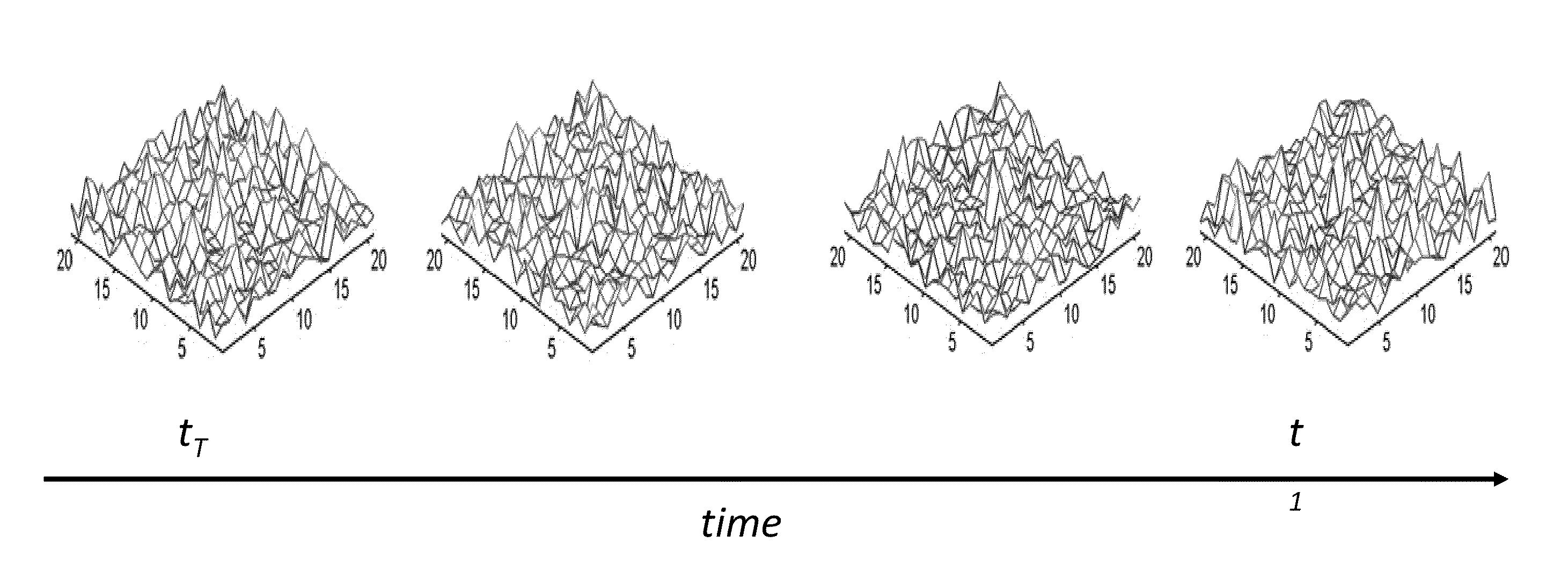
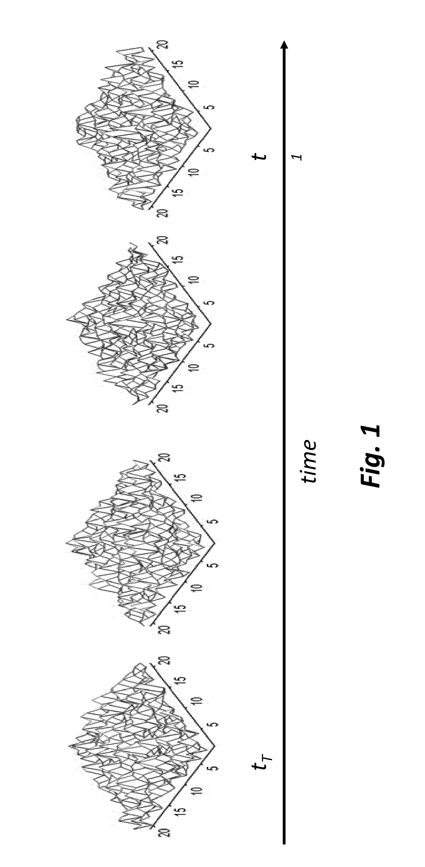
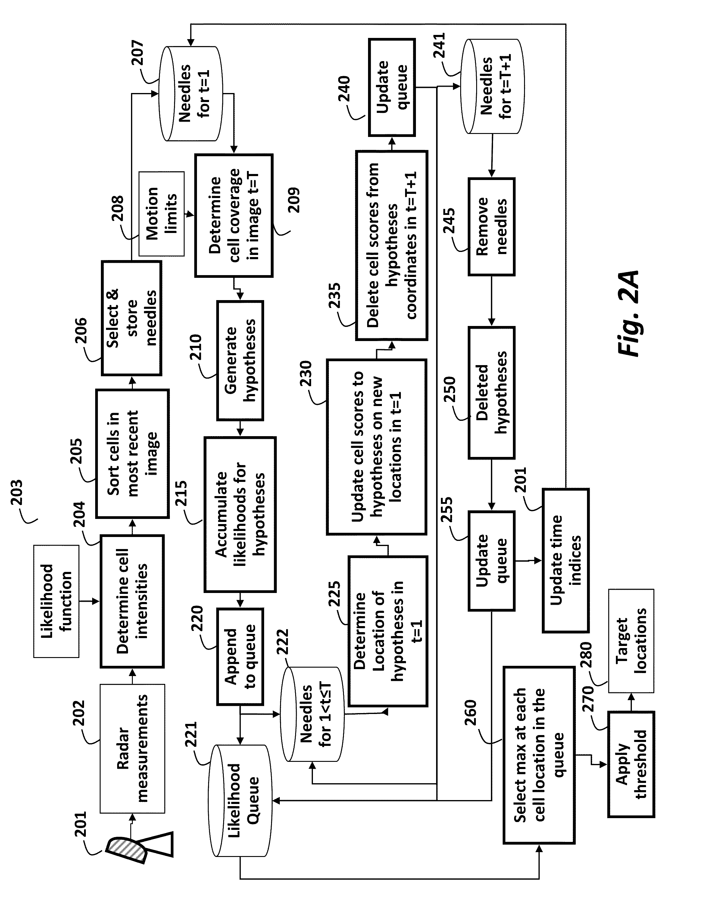
[0030]As shown in FIGS. 2A and 2B, the embodiments of the invention provide a method for detecting small targets from a sequence of radar images using sample based track-before-detection (TBD). The steps of the method can be performed in a processor connected to memory and input / output interfaces as known in the art.

[0031]A radar system 201 acquires radar measurements 202 in a form of a temporal sequence of images. At time t, an input image It for the method includes noise nt, clutter ct, and a target signal zt

It:zt+nt+ct,  (1)

where clutter refers to signals returned from background objects such as ground, sea, atmospheric conditions, including rain, snow, hail, sand storms, clouds, and turbulence, and man-made objects such as buildings, etc. These constituents are assumed to be independent random variables. Noise is typically present in the communication channel, and appears as random variations superimposed on the received signal.

[0032]A state of the target at time t is St

st=[xt...


PUM


Abstract

A method detects a target in a sequence of radar images, wherein each image is partitioned into a grid of cells, and wherein each cell has a corresponding position in an image coordinate system associated with a location in a world coordinate system. For each most recent image in a sliding temporal window of images, intensities of each cell are determined, and the subset of the cells having highest intensities is stored as a set of current needles. A set of hypotheses, obtained by using a state transition model and corresponding maximum limits, is determined for the current set of needles and appended to a set of queues. The hypotheses for the previous sets of needles to the corresponding set of queues are updated, and a maximum likelihood in the set of queues are selected to detect the location of targets.

Description

FIELD OF THE INVENTION[0001]This invention relates generally to detecting targets in radar images, and more particularly to detecting very small targets using sample based track-before-detection.BACKGROUND OF THE INVENTION[0002]In high-end radar systems, the reflected signals from radar emission are amplified, and then filtered to extract a sequence of 2D input image in the form of cells in an image coordinate system. In radar terminology the cells correspond to pixels in conventional images. Each cell corresponds to an intensity (power) of the received signal in a particular spatial location in world coordinate system, defined by a range (bins) and an azimuth (beams). In other words, the coordinates of the cells in the image coordinate system correspond to locations in the world coordinate system.[0003]In addition to a potential target reflection signal, the image also includes noise, electromagnetic interference, and clutter. It is extremely difficult to detect very small targets ...

Claims


Application Information

Patent Timeline
Patent Type & Authority Applications(United States)
IPC IPC(8): G01S13/00
CPCG01S7/2923G01S13/89
Inventor PORIKLI, FATIH M.
Owner MITSUBISHI ELECTRIC RES LAB INC
Why Eureka
Try Eureka