Liquid jet head and liquid jet apparatus

a liquid jet and apparatus technology, applied in printing and other directions, can solve the problems of complicated manufacturing methods, complicated manufacturing steps, and complicated lead-out electrode formation, and achieve the effect of reducing the width of the piezoelectric substrate in the direction of narrow grooves, eliminating complicated wiring patterns, and simplifying the structure for leading the electrodes to the outsid

Inactive Publication Date: 2011-10-06
SII PRINTEK
View PDF0 Cites 7 Cited by
  • Summary
  • Abstract
  • Description
  • Claims
  • Application Information

AI Technical Summary

Benefits of technology

[0022]A liquid jet head according to the present invention includes: a piezoelectric substrate including a plurality of narrow grooves formed therein from a front end to a rear end of a surface of the piezoelectric substrate, the plurality of narrow grooves being separated from one another by side walls formed of a piezoelectric body, the piezoelectric substrate having side wall electrodes for driving on wall surfaces of the side walls, and having, on a top surface thereof in proximity of rear ends of the side walls, lead-out electrodes electrically connected to the side wall electrodes; a cover plate including a manifold which communicates to the plurality of narrow grooves for supplying liquid to the plurality of narrow grooves, the cover plate being bonded to the piezoelectric substrate so as to cover a surface region from the front end to before the lead-out electrodes; and a sealing material for blocking, of channels formed by the cover plate and the plurality of narrow grooves, openings of rear channels communicating to the manifold and formed on the rear end side with respect to the manifold. In other words, the rear channels are sealed by the sealing material, and thus, the need for forming the slanted portions which reflect the outer shape of the dicing blade is eliminated. Thus, the width of the piezoelectric substrate in the direction of the narrow grooves may be reduced. Further, the lead-out electrodes are formed on the top surfaces of the side walls in proximity of the rear end, and thus, a structure for leading the electrodes to the outside may be simplified and the need for forming a wiring pattern through complicated steps is eliminated.

Problems solved by technology

The slanted portions which almost do not function as actuators occupy a considerable proportion of the whole width, which is an obstacle to miniaturization of the ink jet head 50, and to achievement of cost reduction by increasing the number of the piezoelectric substrates which can be manufactured from one wafer.
However, as a tradeoff, formation of the lead-out electrodes for leading to the outside the drive electrodes formed on the side walls is quite complicated.
Therefore, the manufacturing method is quite complicated.
Therefore, the manufacturing steps are quite complicated.
A lot of contacts are required, and thus, it is quite difficult to ensure the reliability of the contacts.

Method used


Image

  • Liquid jet head and liquid jet apparatus
  • Liquid jet head and liquid jet apparatus
  • Liquid jet head and liquid jet apparatus

Examples


first embodiment

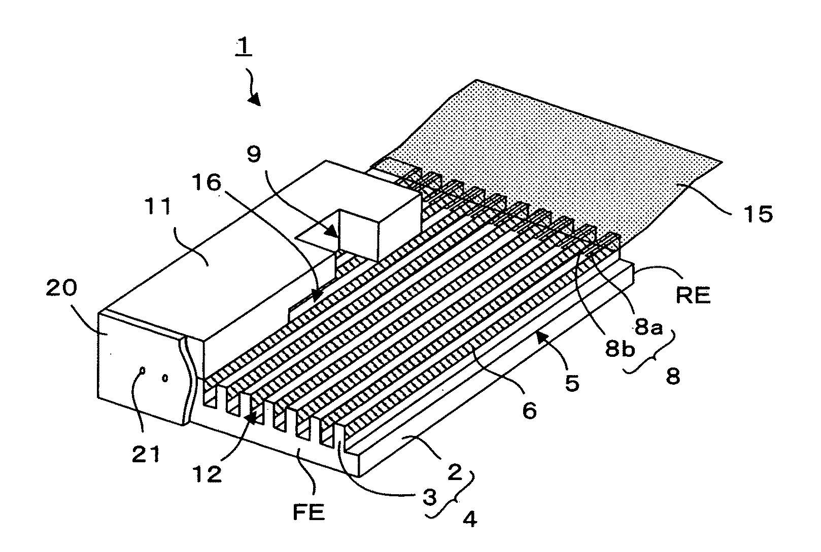
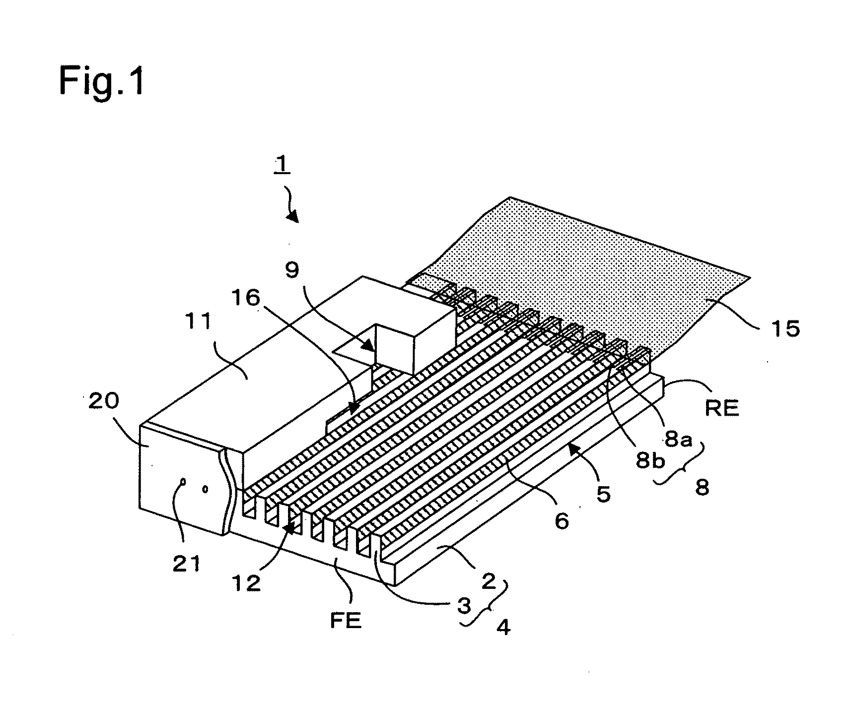
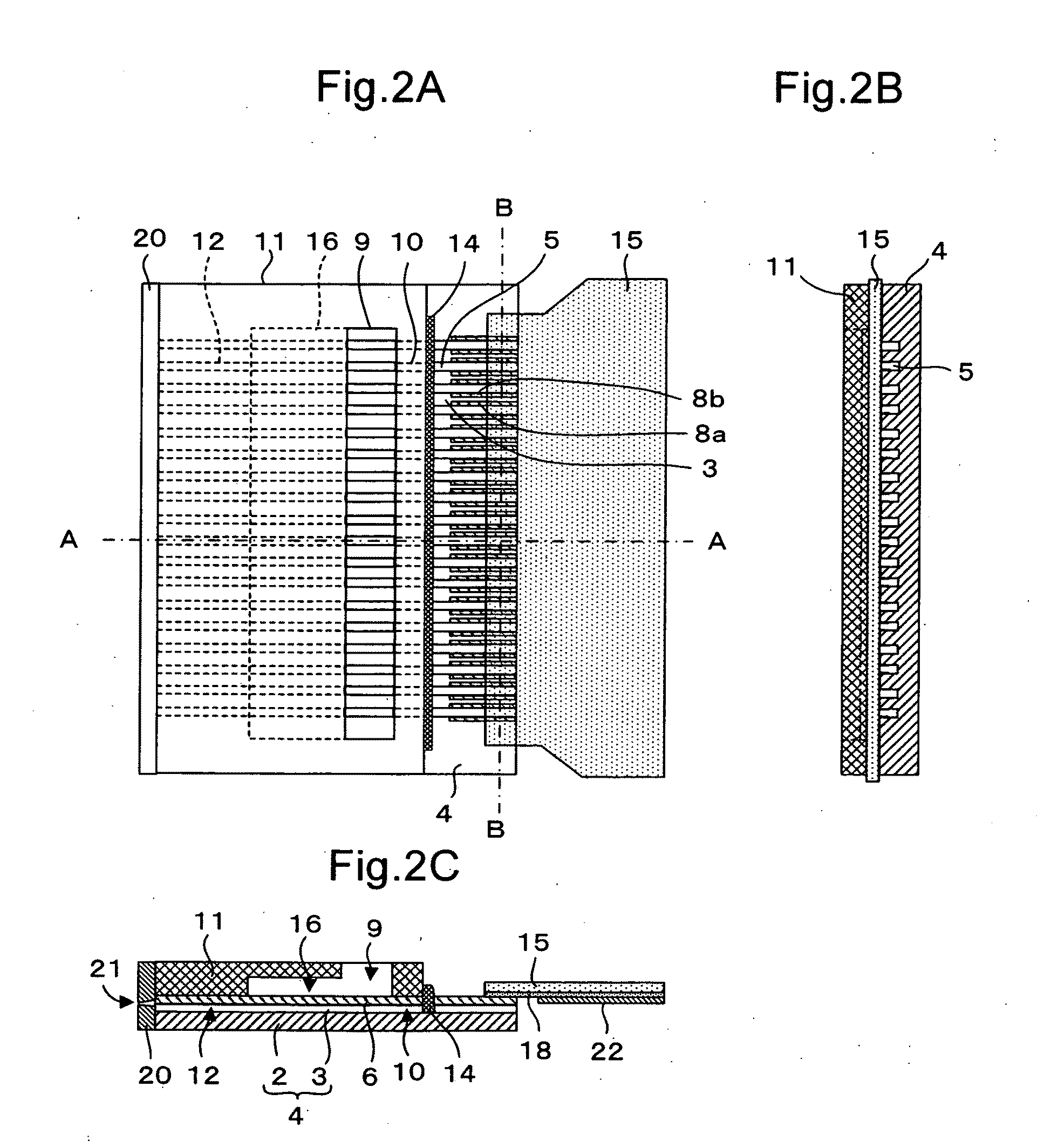
[0044]FIG. 1 is an exploded perspective view of a liquid jet head 1 according to a first embodiment of the present invention. FIG. 2A is a top view of the liquid jet head, FIG. 2B is a side view thereof, and FIG. 2C is a vertical sectional view taken along the line A-A of FIG. 2A of the liquid jet head 1. As illustrated in FIG. 1, the liquid jet head 1 includes a piezoelectric substrate 4 including a substrate 2 and side walls 3 formed on a surface thereof, a cover plate 11 bonded to a surface of the piezoelectric substrate 4, a nozzle plate 20 provided at a front end FE of the piezoelectric substrate 4, a flexible substrate 15 provided on a top surface of the piezoelectric substrate 4 in proximity to a rear end RE of the piezoelectric substrate 4, and a sealing material 14 (omitted in FIG. 1) provided at a corner formed by an end surface of the cover plate 11 on the rear end RE side and the piezoelectric substrate 4.

[0045]The piezoelectric substrate 4 includes a plurality of narrow...

second embodiment

[0054]FIG. 4 is a vertical sectional view of the liquid jet head 1 according to a second embodiment of the present invention. FIG. 4 is different from FIG. 2C, which illustrates the first embodiment, in that the sealing material 14 is provided at openings of the rear channels 10 which are open to the manifold 9. The rest of the structure is similar to that of the first embodiment, and therefore, description thereof is omitted.

[0055]The openings, at which the rear channels 10 communicating to the manifold 9 and the recessed portion 16 are open to the manifold 9 side, are sealed by the sealing material 14. This prevents liquid from flowing in the rear channels 10, and thus, the liquid does not accumulate in the rear channels 10. By eliminating liquid accumulation in the rear channels 10, liquid in the discharge channels 12 and the manifold 9 may be easily replaced, which can promptly remove bubbles and dust that get in the liquid. Note that, the present invention is not limited to pro...

third embodiment

[0056]FIG. 5 is an exploded perspective view of a liquid jet head 1 according to a third embodiment of the present invention. FIG. 6A is a top view of the liquid jet head 1, FIG. 6B is a schematic top view illustrating a connecting state of electrodes, FIG. 6C is a vertical sectional view taken along the line C-C of FIG. 2A of the liquid jet head 1, and FIG. 7 is a partially vertical sectional view taken along the line D-D of FIG. 6A. Like reference symbols are used to designate like members or members having like functions.

[0057]As illustrated in FIG. 5 and FIGS. 6A to 6C, the liquid jet head 1 includes the piezoelectric substrate 4 having the substrate 2 and the side walls 3 formed in the surface thereof, the cover plate 11 bonded to the surface of the piezoelectric substrate 4, the nozzle plate 20 provided at the front end FE of the piezoelectric substrate 4, the flexible substrate 15 provided on the top surface of the piezoelectric substrate 4 in proximity of the rear end RE of ...


PUM


Abstract

The liquid jet head (1) includes: a piezoelectric substrate (4) including a plurality of grooves (5) which are formed therein from a front end (FE) to a rear end (RE) of a surface of the substrate and separated from one another by side walls (3), the piezoelectric substrate having lead-out electrodes (8) formed on top surfaces of the side walls (3); a cover plate (11) which includes a manifold (9) and is bonded to the surface of the piezoelectric substrate (4); and a sealing material (14) for blocking, of channels formed by the cover plate (11) and the grooves (5), openings of rear channels (10) formed on the rear end (RE) side with respect to the manifold (9).

Description

TECHNICAL FIELD[0001]The present invention relates to a liquid jet head for forming an image, a character, or a thin film material on a recording medium by discharging liquid from a nozzle and to a liquid jet apparatus using the same.BACKGROUND ART[0002]In recent years, there has been used an ink jet type liquid jet head for discharging ink droplets on recording paper or the like to render a character or graphics or for discharging a liquid material on a surface of an element substrate to form a pattern of a functional thin film. In such a liquid jet head, ink or a liquid material is supplied from a liquid tank via a supply tube to the liquid jet head, the ink is caused to fill minute space formed in the liquid jet head, and the capacity of the minute space is momentarily reduced according to a drive signal to discharge a liquid droplet from a nozzle which communicates to a groove.[0003]FIG. 12 is an exploded perspective view of an ink jet head 50 of this type. FIG. 13A is a top vie...

Claims


Application Information

Patent Timeline
Patent Type & Authority Applications(United States)
IPC IPC(8): B41J2/045
CPCB41J2002/14491B41J2/14209B41J2/175B41J2/045
Inventor KOSEKI, OSAMU
Owner SII PRINTEK
Why Eureka
Try Eureka