Compound eye photographing method and apparatus

a compound eye and photographing technology, applied in the field of photographing methods with cameras, can solve the problems of not being able to perform photographing in the field of photographs, and achieve the effect of reducing processing volume and quick focusing processing

Inactive Publication Date: 2011-10-06
FUJIFILM CORP
View PDF6 Cites 16 Cited by
  • Summary
  • Abstract
  • Description
  • Claims
  • Application Information

AI Technical Summary

Benefits of technology

[0047]Further, the compound eye photographing apparatus in accordance with the present invention may be modified such that the objects acting as targets of the focusing are previously registered in the registering means, the objects having been registered in the registering means are recognized at the time of the detection of the objects in the live view images, and the thus recognized objects having been registered in the registering means are taken as the detected objects. With the modification described above, the effects described below are obtained. Specifically, with the modification described above, in cases where the images of many objects, such as persons, are present in the live view images, the photographing operation is performed by eliminating unnecessary objects and by focusing on only the objects, which the user desires to photograph. Also, since the unnecessary objects are eliminated, the amount of the processing becomes small, and the focusing processing is performed quickly.
[0048]In such cases, the compound eye photographing apparatus in accordance with the present invention may be modified such that the objects inputted by the user are taken as the objects to be registered. With the modification described above, the level of probability that the photographing operation will be performed by focusing on the objects, which the user desires to photograph, is enhanced.
[0050]Also, the compound eye photographing apparatus in accordance with the present invention may be modified such that the object movement is detected in accordance with the calculated object movement distance, and the object, the movement of which is not detected, is excluded from the target of the focusing. With the modification described above, the focusing on the object which is not moving is avoided, and therefore the level of probability that the photographing operation will be performed by focusing on the objects, such as persons, on which the focusing is to be performed, is enhanced.
[0052]Further, the compound eye photographing apparatus in accordance with the present invention may be modified such that the apparatus further comprises a registering section for registering predetermined objects as the objects to be detected, and an object recognizing section for recognizing an object, which has been registered in the registering section, from the live view images outputted by the imaging sections and thus acting as the object detecting section. With the modification described above, incases where the images of many objects, such as persons, are present in the live view images, the photographing operation is performed by eliminating unnecessary objects and by focusing on only the objects, which the user desires to photograph. Also, since the unnecessary objects are eliminated, the amount of the processing becomes small, and the focusing processing is performed quickly.

Problems solved by technology

With each of the automatic focus adjusting apparatuses described in Japanese Unexamined Patent Publication Nos. 5(1993)-027157 and 7(1995)-199059, although it is possible for the photographing to be performed by focusing on a single moving object, it is not always possible for the photographing to be performed by focusing on each of the two objects, which are moving in the manner described above.

Method used


Image

  • Compound eye photographing method and apparatus
  • Compound eye photographing method and apparatus
  • Compound eye photographing method and apparatus

Examples


first embodiment

[0116]FIGS. 4A and 4B are flow charts showing a flow of photographing processing in the compound eye photographing method carried out in the digital camera 1. The flow of the processing with respect to the compound eye photographing operation, which is performed with the digital camera 1 by automatically focusing on each of two objects, will be described hereinbelow with reference to FIGS. 4A and 4B. In the explanation made hereinbelow, unless otherwise specified, the processing performed automatically is performed basically in accordance with the control of the CPU 110.

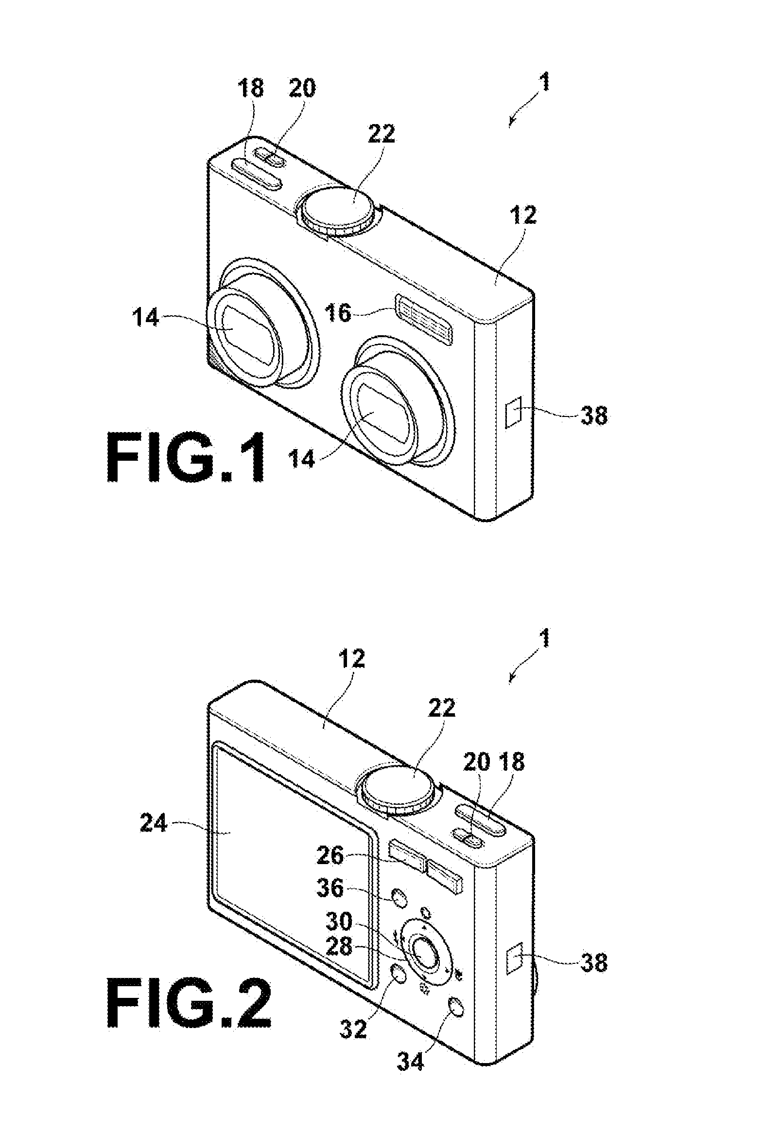
[0117]In this case, the aforesaid mode dial 22 is set at the “2 objects tracking” position, the shutter button 18 is pressed halfway, and the photographing operation is begun. In a step S1, the CPU 110 performs the processing for fetching the live view images, i.e. the processing for fetching the images signals, which are successively outputted in units of a frame from the right imaging system 10R and the left imagin...

second embodiment

[0129]A flow of processing in the compound eye photographing method in accordance with the present invention will be described hereinbelow with reference to FIGS. 7A and 7B. In FIGS. 7A and 7B, similar steps are numbered with the same reference numerals with respect to FIGS. 4A and 4B. As for FIGS. 7A and 7B (and those that follow), if it is not necessary particularly, the explanation of the similar steps will be omitted.

[0130]The method illustrated in FIGS. 7A and 7B is basically identical with the method illustrated in FIGS. 4A and 4B, except that a step S30 and a step S31 are performed between the step S15 and the step S16, and except that a step S32 and a step S33 are performed between the step S16 and the step S17. Specifically, in this embodiment, in the step S32, a priority degree update operation is performed, for example, by specifying the image of the specific object Oi on the monitor 24 constituted of a touch panel with finger touching. In cases where the priority degree ...

third embodiment

[0134]A flow of processing in the compound eye photographing method in accordance with the present invention will be described hereinbelow with reference to FIGS. 8A and 8B. The method illustrated in FIGS. 8A and 8B is basically identical with the method illustrated in FIGS. 4A and 4B, except that a step S40 is performed between the step S15 and the step S16. Specifically, in this embodiment, in lieu of the priority degree being updated by the operation performed by the user as in the method illustrated in FIGS. 7A and 7B, in the step 40, the priority degrees with respect to a plurality of the objects Oi are updated automatically at the time of every variation of the frame of the live view images.

[0135]In cases where the same objects are imaged successively in the live view images, if the same objects are moving, the composition in each frame will vary, and therefore there will be the possibility that the priority degrees having already been adjusted will not be adapted to the compo...


PUM


Abstract

An object is detected from live view images photographed by two imaging sections, correspondence relationship of the detected object is detected between the two live view images and between previous and current frames, and priority degrees of detected objects are adjusted. A distance from a camera to the object is calculated, and an object movement distance between the frames is calculated from an amount of change of the camera-to-object distance, which change occurs between the frames of the live view images. A focusing position for each of objects of the highest and second highest priority degrees and for each of the next and subsequent frames is predicted from the object movement distance. Photographing is performed by focusing on each of the objects of the highest and second highest priority degrees at each of the two imaging sections in accordance with each of the predicted focusing positions.

Description

BACKGROUND OF THE INVENTION[0001]1. Field of the Invention[0002]This invention relates to a photographing method with a camera, or the like. This invention particularly relates to a photographing method, wherein automatic focusing is performed on moving objects in anticipation of the movements of the objects.[0003]This invention also relates to a photographing apparatus for carrying out the photographing method described above.[0004]2. Description of the Related Art[0005]Heretofore, there have been proposed various photographing apparatuses, such as cameras, wherein automatic focusing is performed on a moving object in anticipation of an amount of the movement occurring after a distance survey has been made.[0006]For example, in Japanese Unexamined Patent Publication No. 5(1993) -027157, an automatic focus adjusting apparatus is disclosed, wherein a direction of relative movement of an object and a movement speed of the object with respect to a direction of a lens optical axis are c...

Claims


Application Information

Patent Timeline
Patent Type & Authority Applications(United States)
IPC IPC(8): H04N5/232H04N5/228
CPCH04N5/2251H04N5/2258H04N5/23293H04N5/23219H04N5/23245H04N5/23212G02B27/646H04N23/45H04N23/50H04N23/673H04N23/61H04N23/611H04N23/667H04N23/63
Inventor EGO, SHUNTA
Owner FUJIFILM CORP
Why Eureka
Try Eureka