Knock control device of internal combustion engine

a control device and internal combustion engine technology, applied in the direction of electric control, machines/engines, instruments, etc., can solve the problems of generating vibration which gives a sense of discomfort to occupants, causing a clogging of the upper surface of the piston, and generating vibration. , to achieve the effect of not increasing the cpu load, low cost, and small processing amoun

Active Publication Date: 2014-12-30
MITSUBISHI ELECTRIC CORP +1
View PDF12 Cites 1 Cited by
  • Summary
  • Abstract
  • Description
  • Claims
  • Application Information

AI Technical Summary

Benefits of technology

[0026]The present invention has been made to solve the problems of the related art as described above, and an object of the present invention is to provide a knock control device of an internal combustion engine in which new data for applying the present invention does not need to be obtained, setting man-hours are not increased, the amount of processing to be added is small, and CPU loads are not also increased, whereby low costs and correct knock detection can be achieved.
[0030]Further, there can be obtained a knock control device of an internal combustion engine in which the amount of processing to be added is small, CPU loads are not also increased, and a circuit such as an envelope detection circuit does not need to be added, whereby low costs and correct knock detection can be achieved.

Problems solved by technology

An engine etc. that runs on gasoline ignites and burns air-fuel mixture in a cylinder by a spark from an ignition plug during combustion stroke; however, when pressure in the cylinder is abnormally increased in the middle of flame propagation after ignition, a knock in which an unburned portion of the air-fuel mixture is self-ignited may generate before the flame propagation is completed.
Then, a problem exists in that, when the knock is generated, vibration which gives a sense of discomfort to occupants is generated and, in the worst case, the upper surface of a piston is melted and damaged to break down the engine.
This object is to provide countermeasures against a phenomenon in that, when a load of the engine is increased, the peak hold value is increased in also the case where the knock is not generated, but if stabilization is continued by smoothing processing or limitation processing of updating quantity, the background level is not immediately increased; and as a result, a knock determination value becomes excessively small and therefore the knock is erroneously determined.
On the other hand, the knock may generate when the load of the engine is increased; and a very strong knock may continuously generate in some cases.
As a result, even in the case of the very strong knock signal, determination cannot be made as to whether or not the knock is generated.
Then, separation from the continuous knock generation state described above cannot be made and therefore the knock is continuously generated to cause a serious effect on the engine.
However, in the case where a load of the engine is gradually increased so that a change in the background level is below the upper limit value of updating quantity, the knock cannot be detected as shown in FIG. 3 and separation from the continuous knock generation state cannot be made.
That is, the method which forms the knock determination value based on the peak hold value and detects the knock by comparing with the peak hold value is effective at the time when the load is transited; however, the continuous knock generation state cannot be detected completely by only this method.
However, each method is intended to a previous knock detection system; and therefore, the following problems are generated when applied to a knock detection system in which the background level is defined as a result of primary filter calculation of the knock signal, which is a specification in recent years.
Thus, a problem exists in that costs of the detection circuit and CPU loads by software processing equivalent to the envelope detection are increased.
Furthermore, a problem exists in that the average inclination and the duration time need to be calculated using software; and therefore, CPU loads are increased.
However, the measurement of such values by the actual engine is difficult because it is necessary to set the minimum value by measuring data while continuing a continuous strong knock state that is the continuous knock generation state and by measuring the same at various operation states and loads of the internal combustion engine in order to apply to the detection of the continuous knock generation state during stationary time.
If such evaluation is performed, the engine is damaged, so that a problem of reliability arises in that, as for data obtained during progressive damage, it is impossible to tell where reliable data ends from the beginning of the measurement.
Further, a damaged engine is repaired and evaluation is made by a plurality of engines; and accordingly, there arises a problem in costs.

Method used


Image

  • Knock control device of internal combustion engine
  • Knock control device of internal combustion engine
  • Knock control device of internal combustion engine

Examples


embodiment 1

[0048]The basic concept of the present invention will be described first and then a knock control device of an internal combustion engine according to Embodiment 1 of the present invention will be specifically described in detail with reference to drawings.

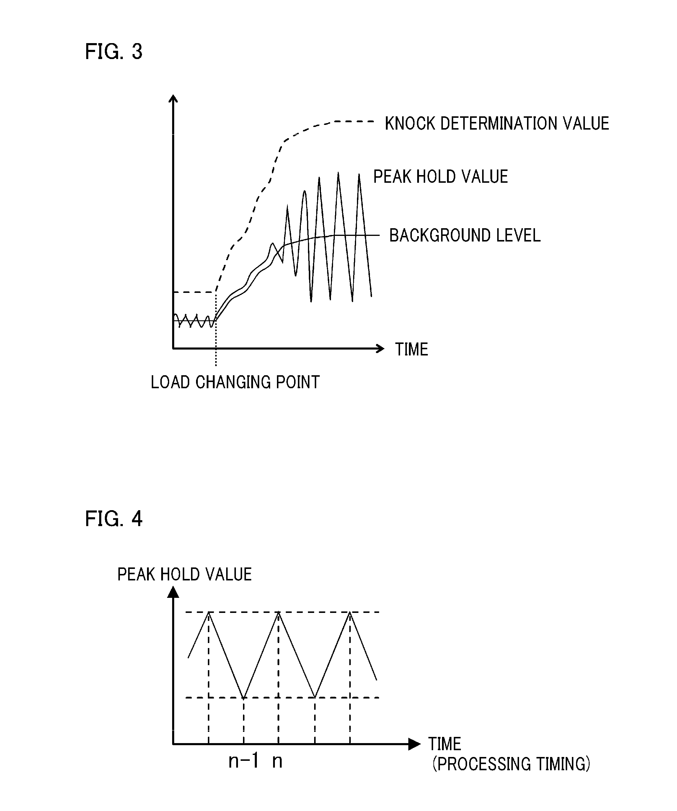
[0049]In the knock control device of the present invention, a background level is defined as a result of primary filter calculation of an output signal from a knock sensor; and therefore, the background level is defined in the following Equation (1):

VBGL(n)=K×VBGL(n−1)+(1−K)×VP(n)  Equation (1)

[0050]where[0051]VBGL(n): background level,[0052]VP(n): peak hold value,[0053]K: filter coefficient, and[0054]n: processing timing (discrete time).

[0055]Incidentally, hereinafter, description will be made that the output signal from the knock sensor is regarded as a peak hold value from the knock sensor; however, the peak hold value of the output signal of the knock sensor may be even an integral value (the area of the higher potential side ...

embodiment 2

[0138]A knock control device of an internal combustion engine according to Embodiment 2 of the present invention will be described. The different point between Embodiment 2 and Embodiment 1 is only a method of calculating a maximum value L of a variation of a peak hold value; and therefore, only this portion will be described.

[0139]The maximum value L of the variation of the peak hold value is defined depending on the engine speed ne of the internal combustion engine. In the method of setting L, as in Embodiment 1, data of peak hold values in various operation states and loads of the internal combustion engine in which a knock is not generated are obtained and maximum values of the variation thereof are classified by the engine speed ne of the internal combustion engine to set as table data. This is L shown in FIG. 6 and, for example, is set as FIG. 11.

[0140]In the maximum value L of the variation of the peak hold value of 25 of FIG. 9, the table of FIG. 11 is interpolated with the ...

embodiment 3

[0145]A knock control device of an internal combustion engine according to Embodiment 3 of the present invention will be described. The different points between Embodiment 3 and Embodiment 1 are a portion of a knock correction quantity calculation section 28 shown in FIG. 9 and a portion from step S10 that determines the presence or absence of the generation of a stationary knock to step S19 that calculates knock correction quantity θR(n) in FIG. 10; and therefore, only these portions will be described.

[0146]In the portion of the knock correction quantity calculation section 28 shown in FIG. 9 in Embodiment 3, the case where the number of repeating times, in which a determination that “stationary knock is generated” is held for a predetermined processing timing T1 when the stationary knock is generated and a determination that “next stationary knock is generated” is established within its hold time, becomes predetermined times T2, is regarded as the determination that “stationary kn...


PUM


Abstract

In a knock control device of an internal combustion engine equipped with a control unit which updates a background level based on an output signal from a knock sensor and detects the generation of a knock by comparing a variation of the background level with a knock determination value, a determination as to whether the knock is generated is performed by((variation of first filter value of peak hold value)>((1−filter coefficient) / (1+filter coefficient)×(predetermined value larger than maximum value of variation of peak hold value in case where knock is not generated))).

Description

BACKGROUND OF THE INVENTION[0001]1. Field of the Invention[0002]The present invention relates to a knock control device of an internal combustion engine equipped with a knock control unit which calculates a background level based on a detected knock signal of the internal combustion engine and performs knock determination by comparing a variation of background level with a knock determination value.[0003]2. Description of the Related Art[0004]An engine etc. that runs on gasoline ignites and burns air-fuel mixture in a cylinder by a spark from an ignition plug during combustion stroke; however, when pressure in the cylinder is abnormally increased in the middle of flame propagation after ignition, a knock in which an unburned portion of the air-fuel mixture is self-ignited may generate before the flame propagation is completed. Then, a problem exists in that, when the knock is generated, vibration which gives a sense of discomfort to occupants is generated and, in the worst case, the...

Claims


Application Information

Patent Timeline
Patent Type & Authority Patents(United States)
IPC IPC(8): G06F19/00
CPCF02P5/152F02D35/027G01L23/225Y02T10/46F02D2041/286
Inventor TANAKA, TORUMATSUSHIMA, YUHEIEZUMI, KEITAROKUSUNOKI, TOMOKUNIINOUE, ATSUSHIMORIMOTO, HIROKI
Owner MITSUBISHI ELECTRIC CORP
Why Eureka
Try Eureka