
Dynamic DC offset canceling apparatus and dynamic DC offset canceling method

a technology of dc offset cancellation and apparatus, which is applied in the direction of dc level restoring means or bias distort correction, line-faulst/interference reduction, and baseband system details, etc., can solve the problem of delayed distortion in the received signal, bit error rate characteristics deterioration, and faster symbol rate generating larger delay distortion. , to achieve the effect of small processing amoun

Inactive Publication Date: 2011-10-04
PANASONIC CORP
View PDF8 Cites 0 Cited by
  • Summary
  • Abstract
  • Description
  • Claims
  • Application Information

AI Technical Summary

Benefits of technology

The solution effectively detects and cancels dynamic DC offset with high accuracy, reducing processing complexity and enhancing bit error rate characteristics, particularly in GSM communication systems, while maintaining receiver performance.

Problems solved by technology

Therefore, delay distortion is produced in the received signal and bit error rate characteristics deteriorate.
Faster symbol rates produce larger delay distortion, and so with future high-speed digital mobile communication equipment, the influence of delay distortion cannot be ignored, and cancellation of delay distortion becomes essential.
However, to accompany the spread of the direct conversion reception scheme, in the narrow band digital modulation scheme used in GSM and the like, the received signal frequency is equal to a local frequency, and so the DC offset component remains in a detection output of the receiver (baseband received signal), and, in particular in GSM, DC offset (hereinafter “dynamic DC offset”) increases rapidly in the middle of the burst, and, as a result, DC offset may become difficult to cancel by estimating an average value of the received signals, which may result in deterioration of bit error rate characteristics.
Further, in GSM, known codes (training sequence) for acquiring synchronization and assisting reception are embedded in the middle of the burst, and dynamic DC offset in the middle of the burst deteriorates bit error rate characteristics significantly.
However, a problem with such a conventional DC offset canceling apparatus is that calculation for determining the center point for an arbitrary consecutive subset of digital baseband signals increases the amount of processing.

Method used


Image

  • Dynamic DC offset canceling apparatus and dynamic DC offset canceling method
  • Dynamic DC offset canceling apparatus and dynamic DC offset canceling method
  • Dynamic DC offset canceling apparatus and dynamic DC offset canceling method

Examples


embodiment 1

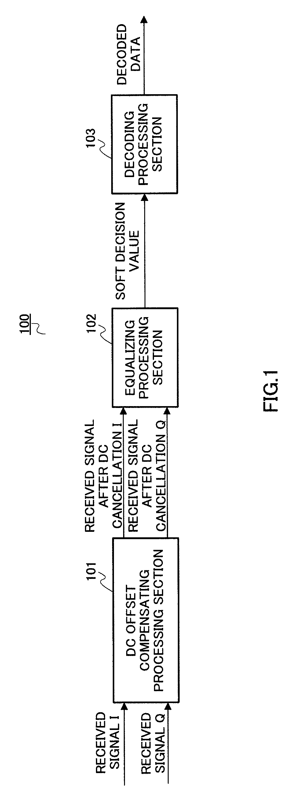
[0027]FIG. 1 is a block diagram showing the configuration of a receiver with the dynamic DC offset canceling apparatus according to Embodiment 1 of the present invention. The present embodiment is an example where the present invention is applied to a digital mobile communication receiver adopting the GSM scheme.

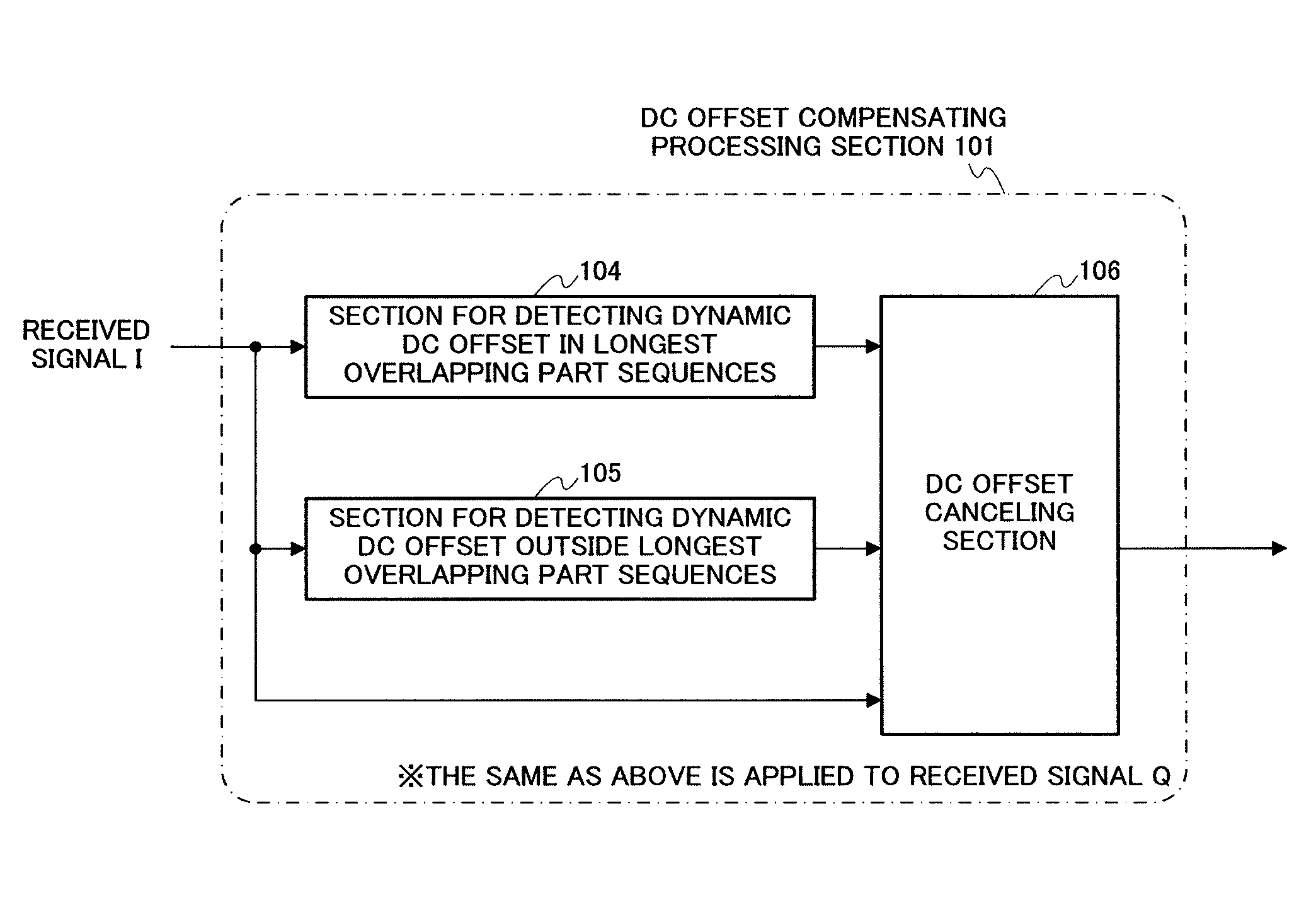
[0028]In FIG. 1, receiver 100 with a dynamic DC offset canceling apparatus is configured with: DC offset compensating processing section 101 that receives as input received signals I and Q which are converted to digital baseband signals and cancels the DC offset from the received signals I and Q; equalizing processing section 102 that equalizes the received signals subjected to DC offset compensating processing; and decoding processing section 103 that decodes the received signals equalized by equalizing processing section 102.

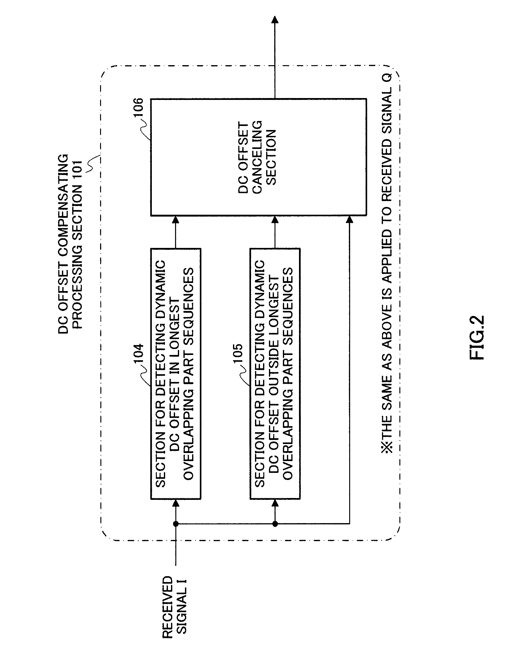
[0029]FIG. 2 shows the configuration of above-described DC offset compensating processing section 101. The same processing is performed for the I-phas...

embodiment 2

[0096]FIG. 9 is a block diagram showing the configuration of a receiver with the dynamic DC offset canceling apparatus according to Embodiment 2 of the present invention and is an example of applying adaptive threshold fluctuation to dynamic DC offset detection and cancellation. The components that are the same as those in FIG. 1 will be assigned the same reference numerals.

[0097]In FIG. 9, receiver 700 with a dynamic DC offset canceling apparatus is configured with: DC offset compensating processing section 101 that receives as input received signals I and Q which are converted to digital baseband signals, and cancels DC offset from the received signals I and Q; equalizing processing section 102 that equalizes the received signals subjected to DC offset compensating processing; decoding processing section 103 that decodes the received signals equalized by equalizing processing section 102; received quality measuring section 704 that receives the signals as input and measures receiv...

embodiment 3

[0099]FIG. 10 is a block diagram showing the configuration of the receiver with the dynamic DC offset canceling apparatus according to Embodiment 3 of the present invention and is an example of applying the present invention to dynamic DC offset detection and cancellation using timing offset information. The components that are the same as those in FIG. 1 will be assigned the same reference numerals.

[0100]InFIG. 10, receiver 800 with a dynamic DC offset canceling apparatus is configured with: DC offset compensating processing section 101 that receives as input, received signals I and Q which are converted to digital baseband signals and cancels a DC offset from the received signals I and Q; equalizing processing section 102 that equalizes the received signals subjected to DC offset compensating processing; decoding processing section 103 that decodes the received signals equalized by equalizing processing section 102; and timing offset detecting section 804 that receives the receive...


PUM


Abstract

The dynamic DC offset canceling apparatus includes: section 104 that detects dynamic DC offset in longest overlapping part sequences from the differences between the sampling values of a first longest overlapping part sequence and the sampling values of a second longest overlapping part sequence, the first longest overlapping part sequence and the second longest overlapping part sequence being overlapping part sequences in a training sequence of the received signal; section 105 that detects dynamic DC offset outside the longest overlapping part sequences from the difference between an average value of sampling values of a received signal which exists in a burst before the first longest overlapping part sequence, and an average value of sampling values of a received signal which exists in a burst after the second longest overlapping part sequence; and section 106 that adaptively subtracts a DC offset value from the received signal based on these results.

Description

CROSS REFERENCE TO RELATED APPLICATIONS[0001]The disclosure of Japanese Patent Application No. 2007-142110, filed on May 29, 2007, including the specification, drawings and abstract, is incorporated herein by reference in its entirety.BACKGROUND OF THE INVENTION[0002]1. Field of the Invention[0003]The present invention relates to a dynamic DC offset canceling apparatus and a dynamic DC offset canceling method for a receiver in wireless communication, and primarily relates to a dynamic DC offset canceling apparatus and a dynamic DC offset canceling method used in the receiver having a radio section adopting the direct conversion scheme in digital mobile communication.[0004]2. Description of Related Art[0005]The receiver in digital mobile communication receives radio waves from a plurality of paths with different propagation times, due to the influence of multipath fading which may occur in a radio link. Therefore, delay distortion is produced in the received signal and bit error rate...

Claims


Application Information

Patent Timeline
Patent Type & Authority Patents(United States)
IPC IPC(8): H04L25/06
CPCH04L25/061
Inventor TAKAGI, NOBUHIROMURAO, YUKITERUYUI, TOMOHIROURAMOTO, YASUTAKATAGUCHI, ATSUSHISUZUKI, KOJIKAWAI, YOSHINAO
Owner PANASONIC CORP
Learn More