Parameter determination apparatus, signal transmission apparatus, parameter determination method, signal transmission method and program recording medium

Pending Publication Date: 2022-03-17
NEC CORP
View PDF0 Cites 0 Cited by
  • Summary
  • Abstract
  • Description
  • Claims
  • Application Information

AI Technical Summary

Benefits of technology

The patent aims to provide a solution for determining parameters and transmitting signals using a neural network. The aim is to develop a system that requires minimal processing power and can effectively solve complex problems. The technical effects of this invention include reducing processing requirements, increasing efficiency, and improving accuracy.

Problems solved by technology

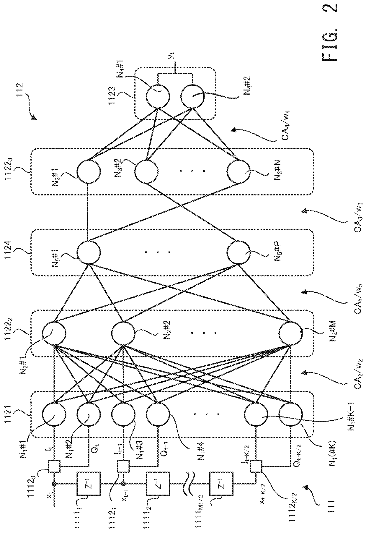
An apparatus that is build by using the neural network has such a technical problem that a processing amount (namely, a calculation amount) is relatively large due to a complication of a network structure of the neural network.

Method used

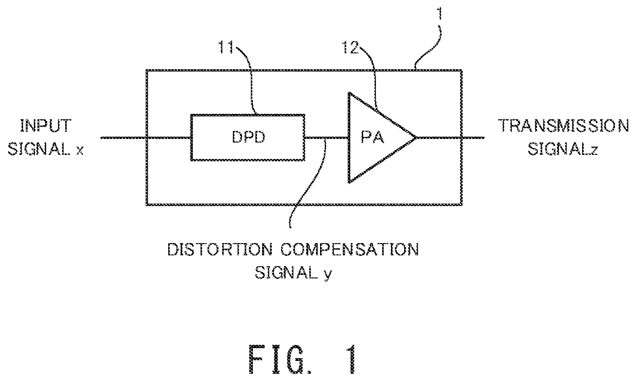

Image

  • Parameter determination apparatus, signal transmission apparatus, parameter determination method, signal transmission method and program recording medium
  • Parameter determination apparatus, signal transmission apparatus, parameter determination method, signal transmission method and program recording medium
  • Parameter determination apparatus, signal transmission apparatus, parameter determination method, signal transmission method and program recording medium

Examples


first modified example

Signal Transmission Apparatus 1a in First Modified Example

[0085]With reference to FIG. 9, a signal transmission apparatus 1a in a first modified example will be described. FIG. 9 is a block diagram that illustrates a configuration of the signal transmission apparatus 1a in the first modified example.

[0086]As illustrated in FIG. 9, the signal transmission apparatus 1a is different from the signal transmission apparatus 1 in that the signal transmission apparatus 1a is an apparatus that is configured to transmit the transmission signal z through an optical communication network (for example, an optical communication line). In this case, the signal transmission apparatus 1a is different from the signal transmission apparatus 1 in that the signal transmission apparatus 1a is provided with an E / O converter 13a that converts the transmission signal z, which is outputted from the power amplifier 12, to an optical signal. As a result, the transmission signal z that is converted to the opti...

second modified example

Signal Transmission Apparatus 1b in Second Modified Example

[0090]Next, with reference to FIG. 10, a signal transmission apparatus 1b in a second modified example will be described. FIG. 10 is a block diagram that illustrates a configuration of the signal transmission apparatus 1b in the second modified example.

[0091]As illustrated in FIG. 10, the signal transmission apparatus 1b is different from the signal transmission apparatus 1 in that the function block for determining the parameters of the neural network 112 is realized in the signal transmission apparatus 1b. Specifically, the signal transmission apparatus 1b is provided with a processing apparatus 15b. The processing apparatus 15b reads a computer program. The computer program read by the processing apparatus 15b may be recorded in any recording medium, as with the computer program read by the processing apparatus 21. The processing apparatus 15b executes the read computer program to control the distortion compensation circ...


PUM


Abstract

A parameter determination apparatus adds a third layer between first and second layers of the neural network. The third layer includes a third node not including a non-linear activation function. Outputs of first nodes of the first layer is inputted to the third node The number of the third node of the third layer is smaller than the number of second nodes of the second layer. The parameter determination apparatus further learns a weight between the third and second layers as a part of the parameters and selects, as a part of the parameters, one valid path used as a valid connecting path in the neural network for each second node from connecting paths that connect the third node and the second nodes on the basis of the learned weight.

Description

INCORPORATION BY REFERENCE[0001]This application is based upon and claims the benefit of priority from Japanese Patent Application No. 2020-156218, filed on Sep. 17, 2020 and Japanese Patent Application No. 2021-133235, filed on Aug. 18, 2021, the disclosure of which is incorporated herein in its entirety by reference.TECHNICAL FIELD[0002]Embodiments of the present disclosure relate to a parameter determination apparatus, a parameter determination method and a program recording medium that are configured to determine a parameter of a neural network, and a signal transmission apparatus, a signal transmission method and a program recording medium that are configured to transmit a signal, for example.BACKGROUND ART[0003]Recently, a utilization of a neural network is studied in various technical fields. For example, in a wireless communication system such as a mobile communication system, a distortion compensation apparatus in a DPD (Digital Pre-Distortion) type is built by using a neur...

Claims


Application Information

Patent Timeline
IPC IPC(8): H04B1/04H04B10/50G06N3/08
CPCH04B1/0475G06N3/082H04B10/50H04B10/2507
Inventor TANIO, MASAAKI
Owner NEC CORP
Why Eureka
Try Eureka