Vehicular lamp

a technology of a vehicle and a lamp body is applied in the field of vehicles, which can solve the problems of difficult to improve and achieve the effect of improving the use efficiency of light from the light source and efficient radiation

Inactive Publication Date: 2011-10-06
KOITO MFG CO LTD
View PDF16 Cites 47 Cited by
  • Summary
  • Abstract
  • Description
  • Claims
  • Application Information

AI Technical Summary

Benefits of technology

[0007]One or more embodiments of the present invention provide a vehicular lamp that can improve a use efficiency of light from a light source by returning light exiting from a rear surface side of a light guide to inside the light guide and radiating such light in an illumination direction.
[0020]According to a vehicular lamp of one or more embodiments of the present invention, incident light from a first light source exits from a second projection surface of a columnar light guide and is reflected by a reflector, after which such light is re-incident from another non-adjacent first projection surface. The light is then wholly reflected by the second projection surface adjacent to that first projection surface and radiated forward. Thus, even if the columnar light guide is slantingly disposed, a use efficiency of light from a light source can be improved by returning light exiting from a rear surface side of the light guide to inside the light guide and efficiently radiating such light in an illumination direction forward of the lamp.

Problems solved by technology

Other light passes through the reflective surface and exits from the rear surface side, making it difficult to improve the use efficiency of light from the light source.

Method used


Image

  • Vehicular lamp
  • Vehicular lamp
  • Vehicular lamp

Examples


Embodiment Construction

[0030]Hereinafter, embodiments of a vehicular lamp according to the present invention will be described based on FIGS. 1 to 8.

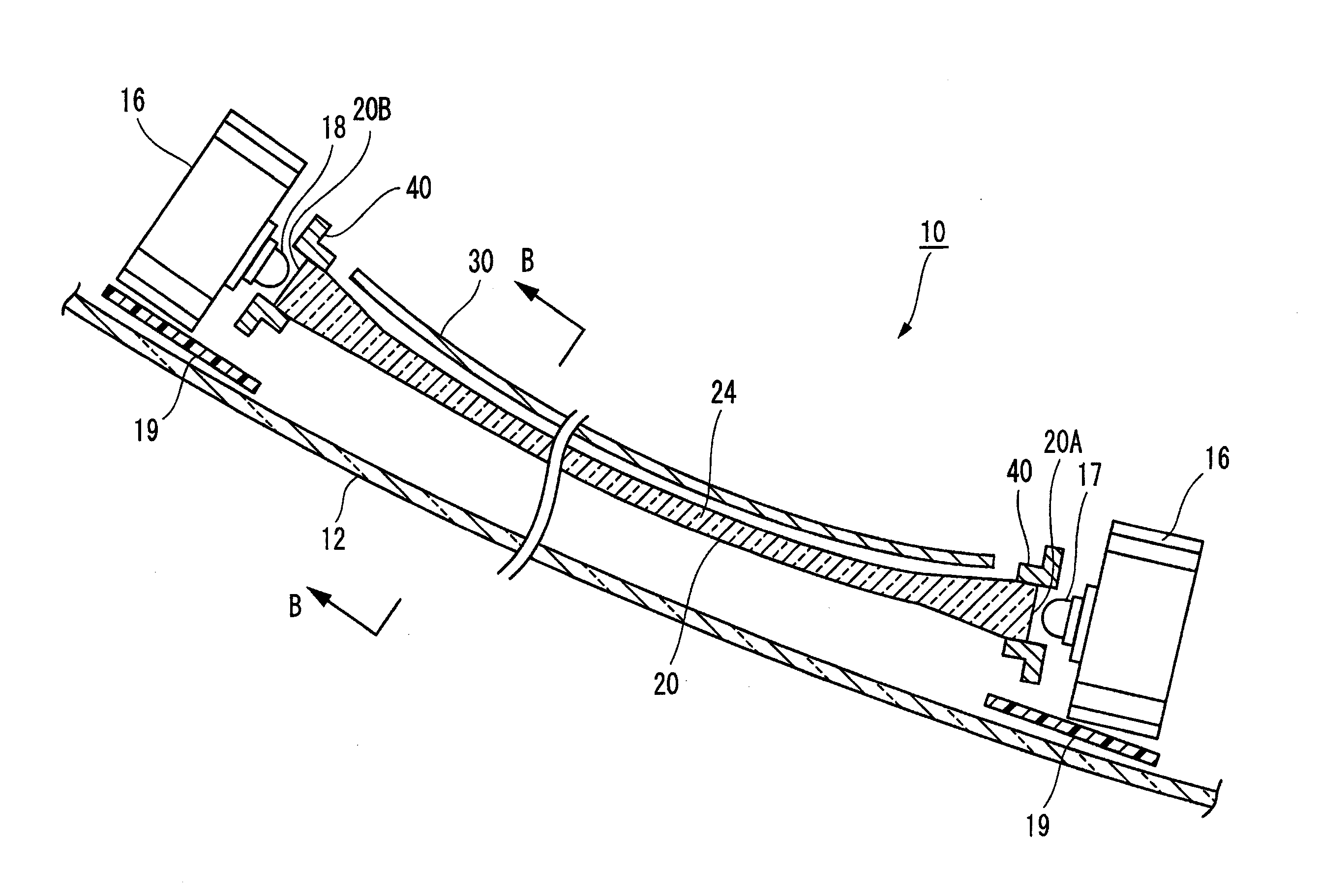
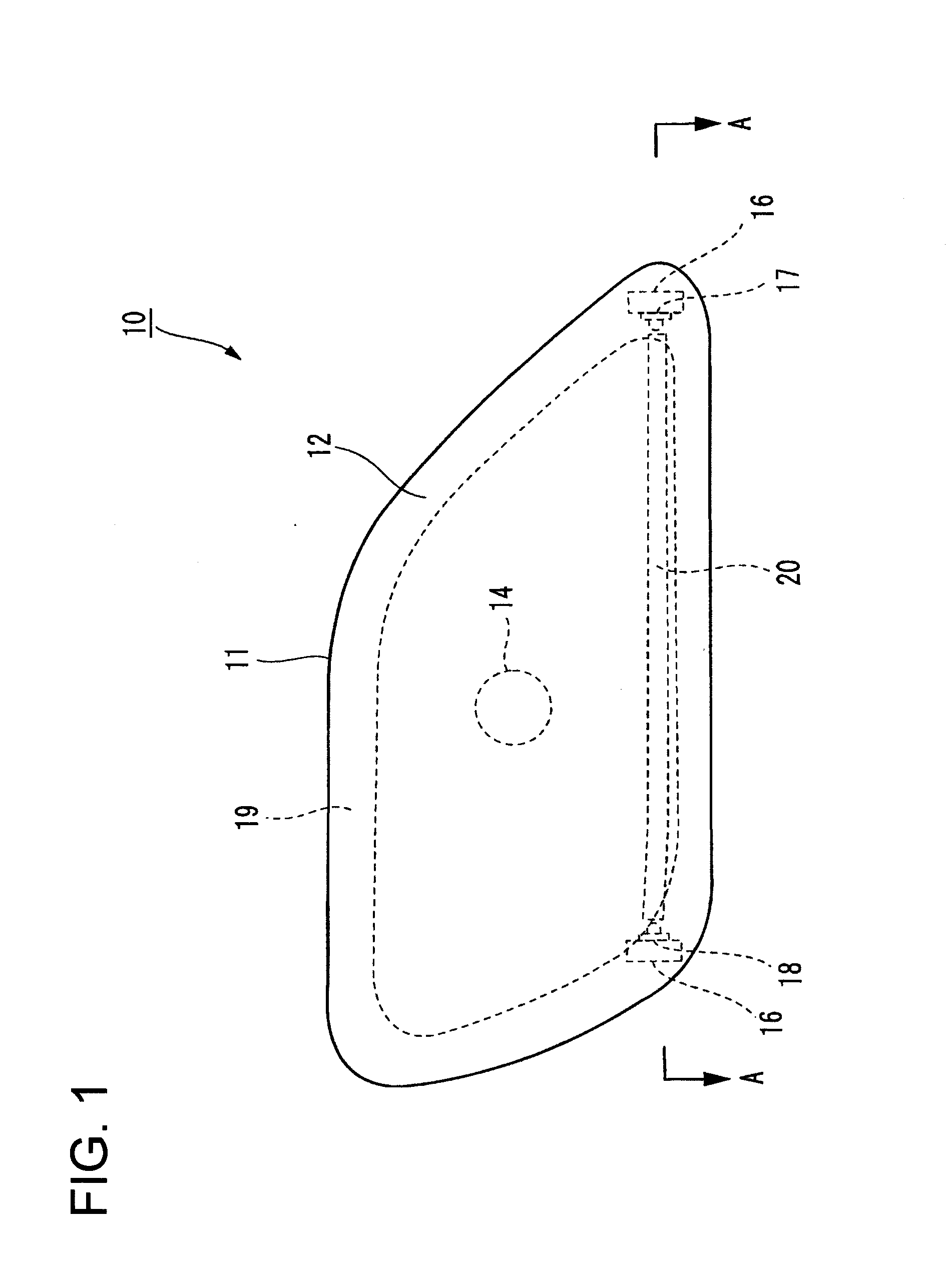
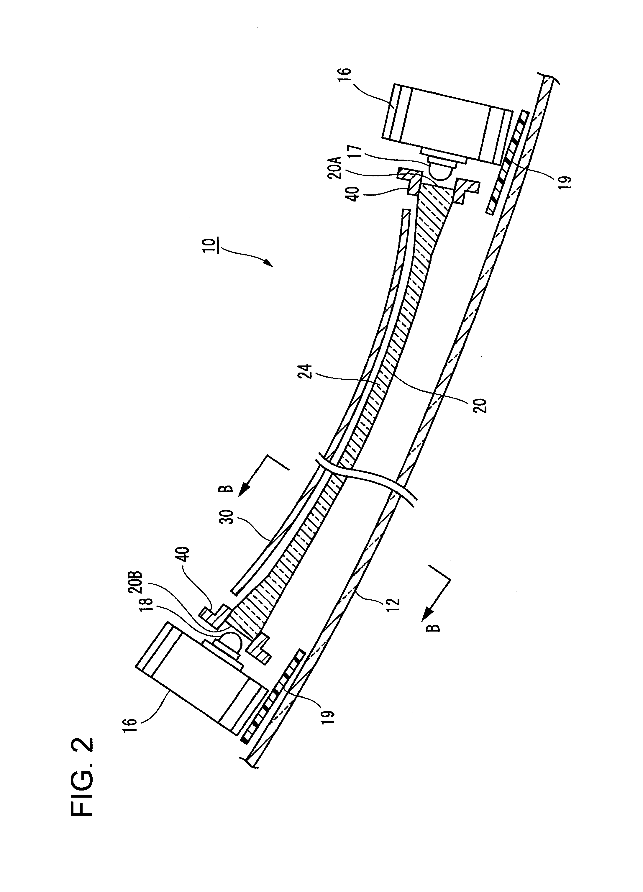
[0031]As shown in FIGS. 1 and 2, a vehicular lamp 10 applied to an indicator lamp of a headlamp that includes a resin lamp body 11 that is fixed to a vehicle body side and whose vehicle front side is formed open, and a colorless and transparent front cover 12 that is attached to an opening portion of the lamp body 11.

[0032]The vehicular lamp 10 further includes a bulb 14 for the headlamp, which is disposed at a center portion inside a lamp chamber that is defined by the lamp body 11 and the front cover 12. The front cover 12 is disposed so as to slant from front to back, that is, from the vehicle body center (right side in the figure) toward the vehicle body side (left side in the figure), and a light guide 20 that is a columnar light guide is disposed curved along the front cover 12. In addition, a reflector 30 is disposed curved near a rear surface side of ...


PUM


Abstract

A light guide includes a first incident portion at an end side thereof near a light source, a stepped portion disposed on a rear surface side thereof in an axial direction and wholly reflects a portion of guided light, and a radiating portion disposed on a front surface side thereof in the axial direction that radiates the wholly reflected light forward. The light guide guides light that is incident through the first incident portion from front to back within the light guide. The stepped portion is a plurality of generally triangular prisms formed continuous in an extension direction, and has, in a cross section that follows an extension axis of the light guide and is parallel to a lamp optical axis, a long first projection surface that extends in the extension direction and a short second projection surface that forms an apex angle with the first projection surface.

Description

BACKGROUND OF INVENTION[0001]1. Field of the Invention[0002]The present invention relates to a vehicular lamp of an automobile or the like, and, more specifically, relates to a vehicular lamp in which light from an LED light source is made incident to a light guide disposed nearby and radiated in an illumination direction from the light guide.[0003]2. Related Art[0004]A conventionally known light emitting device (Patent Document 1, for example) is a light guide in which a triangular notch, that is, a step, is formed on a rear surface side of a light emitting region. By using this notch to form a reflective surface at a predetermined angle, light transmitted from a light source is wholly reflected by the reflective surface and radiated from a front surface side in a predetermined direction.[0005][Patent Document 1] Japanese Patent Application Laid-Open (Kokai) No. H06-201917SUMMARY OF INVENTION[0006]However, in the light guide described above, a portion of the light incident to the r...

Claims


Application Information

Patent Timeline
Patent Type & Authority Applications(United States)
IPC IPC(8): F21V8/00
CPCF21S48/115F21S48/1241F21S48/2281F21S48/2237F21S48/2268F21S48/215F21S41/141F21S41/24F21S43/14F21S43/237F21S43/245F21S43/249
Inventor OKUI, KAZUKIINOUE, AKIOYAMAZAKI, TOMOHARU
Owner KOITO MFG CO LTD
Why Eureka
Try Eureka