Method and Apparatus for Packet Aggregation Transmission

a packet aggregation and transmission method technology, applied in the field of mobile communication, can solve the problems of increasing the transmission time and retransmission time of data packets, the length of aggregated packets, and the system throughput, and achieve the effect of improving the instantaneity of data transmission

Inactive Publication Date: 2011-10-06
SIEMENS AG
View PDF5 Cites 5 Cited by
  • Summary
  • Abstract
  • Description
  • Claims
  • Application Information

AI Technical Summary

Benefits of technology

It is therefore an object of the present invention to provide a method and apparatus for packet aggregation transmission so

Problems solved by technology

It can be seen that in the packet aggregation transmission technology, the throughput and the instantaneity of a system are restrictive to each other, and that although the number of the aggregated subpackets increases the throughput of the system, the number of the aggregated subpackets increases the length of the aggregated packet, thus increasing the transmission time and the retransmission time for the data packets.
The bigger the number of the subpackets, the bigger the system throughput, but the poorer the instantaneity.
Currently, there is no packet aggregation transmission method for point-to-multipoint transmission.
Furthermore, since

Method used


Image

  • Method and Apparatus for Packet Aggregation Transmission
  • Method and Apparatus for Packet Aggregation Transmission
  • Method and Apparatus for Packet Aggregation Transmission

Examples


embodiment i

In the DCF mechanism, each client performs channel access by competition, and only the transmission time sequence of downstream data is collectively controlled by an AP. Therefore, the method in accordance with the presently contemplated embodiment is used for downstream data transmission to clients at the AP side. Under the assumption that there are N clients at this AP in the system, then there is a transmitting cache and transmitting queue respectively for the downstream transmission of these N clients at the AP side.

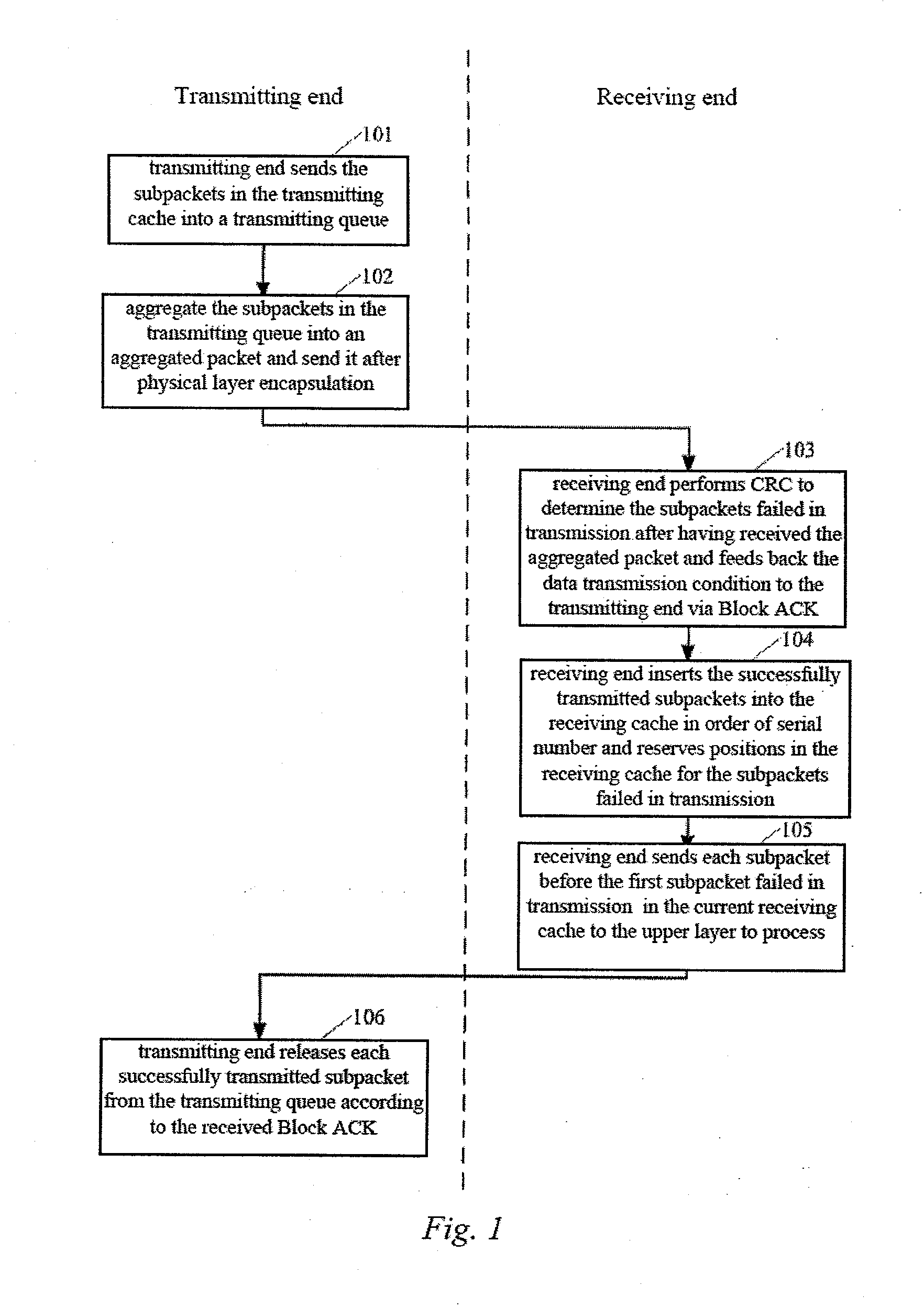
FIG. 4 is a schematic block diagram of the method in accordance with the contemplated embodiment I, where the method particularly comprising the following steps:

Step 401: the largest serial number SiD1 of the subpacket in the transmitting cache corresponding to each client in the AP and the smallest serial number SiD2 of the subpacket in the transmitting queue corresponding to each client at the current transmitting time are determined for each client, where i is an ...

embodiment ii

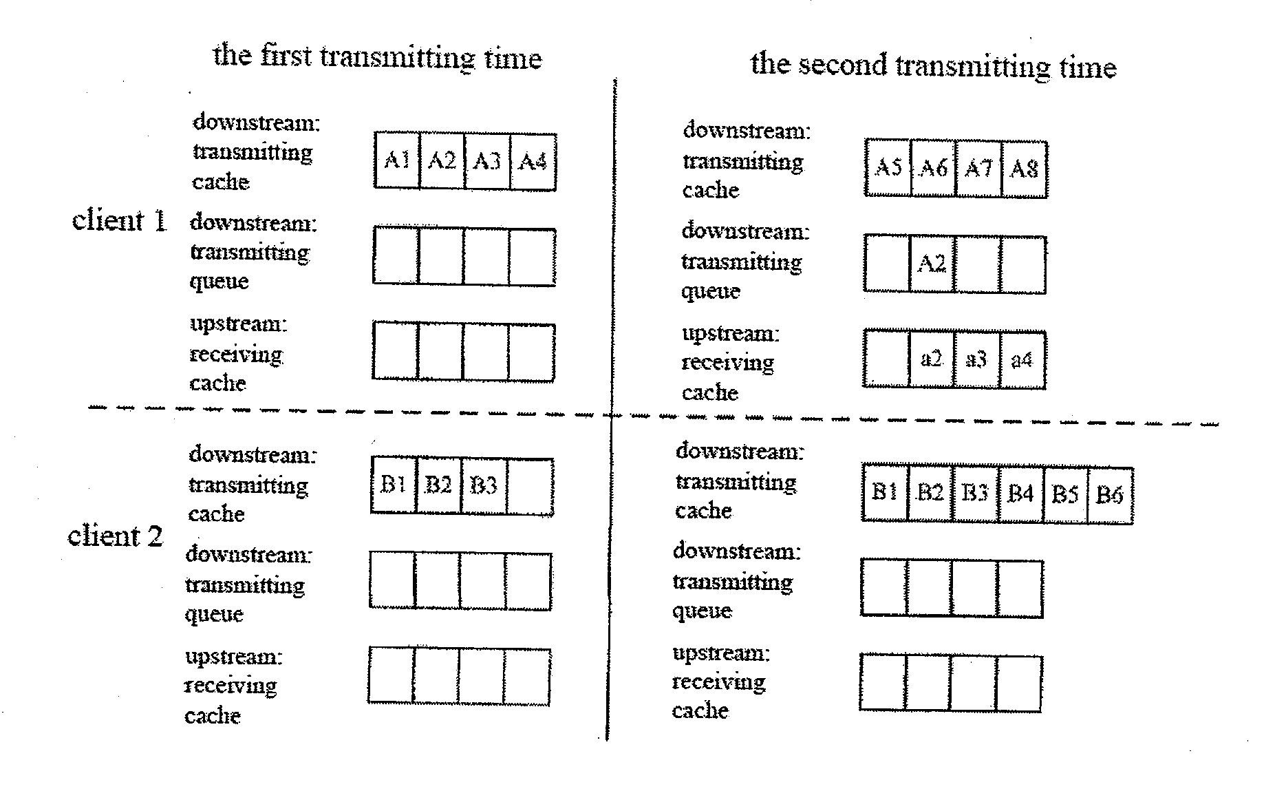
In the PCF mechanism, the upstream and downstream data transmissions are both collectively controlled by the AP, and the AP polls each client in accordance with a preset poll order, and the polled client can perform data transmission when there is data transmission. The PCF mechanism is different from the DCF mechanism in that in the PCF mechanism the transmission urgency of each client needs to consider not only downstream data but also upstream data. Assuming there are N clients at this AP in the system, then there is a transmitting cache and transmitting queue respectively for the downstream transmission of these N clients at the AP side, i.e., simultaneously there are N transmitting caches and N transmitting queues, there are receiving caches respectively for the upstream transmission of these N clients at the AP side, i.e., there are N receiving caches. FIG. 5 is a schematic diagram of a method in accordance with the presently contemplated embodiment, where the method particula...


PUM


Abstract

A method and apparatus for packet aggregation transmission which are for application in a system comprising a transmitting end and at least two receiving ends, wherein the method comprises, for each receiving end, determining respectively a hold-up condition of subpackets at the transmitting and receiving ends at the current transmitting time, and determining the receiving end corresponding to the worst hold-up condition of the subpackets at the transmitting and receiving ends, and performing a packet aggregation transmission to the determined receiving end at the current transmitting time. The present invention is directed to point-to-multipoint data transmission, can solve the problem of transmission time sequence for a plurality of receiving ends, and improves the instantaneity of a system to the maximum degree possible.

Description

BACKGROUND OF THE INVENTION1. Field of the InventionThe present invention relates to the technical field of mobile communication and, more particularly, to a method and apparatus for packet aggregation transmission.2. Description of the Related ArtThe new 802.11n standard is a wireless local area network (WLAN) standard that has been developed rapidly. The 802.11n standard utilizes new technologies in the Media Access Control (MAC) layer and physical layer. Accordingly, the 802.11 n standard has a throughput that is far higher than that of existing WLAN standards, such as 802.11a, 802.11b and 802.11g, which can be up to 600 Mbps. Here, one new technology is packet aggregation, in which each data packet (i.e., a subpacket) that is received from an MAC service access point (SAP) is aggregated as a big aggregated packet that is then transmitted on the physical layer, and only one block response (Block ACK) needs to be fed back for all the subpackets in this aggregated packet rather tha...

Claims


Application Information

Patent Timeline
IPC IPC(8): H04W4/06
CPCH04L1/0007H04L2001/0093H04L1/189H04L1/1887
Inventor KELLER, STEFANLAMPE, MATTIASLI, ZHI JUNTIAN, JI FENG
Owner SIEMENS AG
Why Eureka
Try Eureka