Electronic sphygmomanometer

a sphygmomanometer and electronic technology, applied in the field of sphygmomanometers, can solve the problems of inability to continue measurement while maintaining measurement accuracy, and achieve the effect of maintaining measurement accuracy

Inactive Publication Date: 2011-10-06
OMRON HEALTHCARE CO LTD
View PDF1 Cites 14 Cited by
  • Summary
  • Abstract
  • Description
  • Claims
  • Application Information

AI Technical Summary

Benefits of technology

[0018]One or more embodiments of the present invention enables continuing measurement even if a displacement occurs between the position of a cuff and that of the heart during the measurement. Further, one or more embodiments of the present invention resumes first pressure control after returning an intra-cuff pressure to a pressure value before occurrence of the displacement in order to maintain measurement accuracy.

Problems solved by technology

However, if the posture goes bad during measurement of the blood pressure (the difference in height between the two exceeds a predetermined range), a pressure pulse wave is disturbed, so that it is impossible to continue measurement while maintaining measurement accuracy.

Method used


Image

  • Electronic sphygmomanometer
  • Electronic sphygmomanometer
  • Electronic sphygmomanometer

Examples


Embodiment Construction

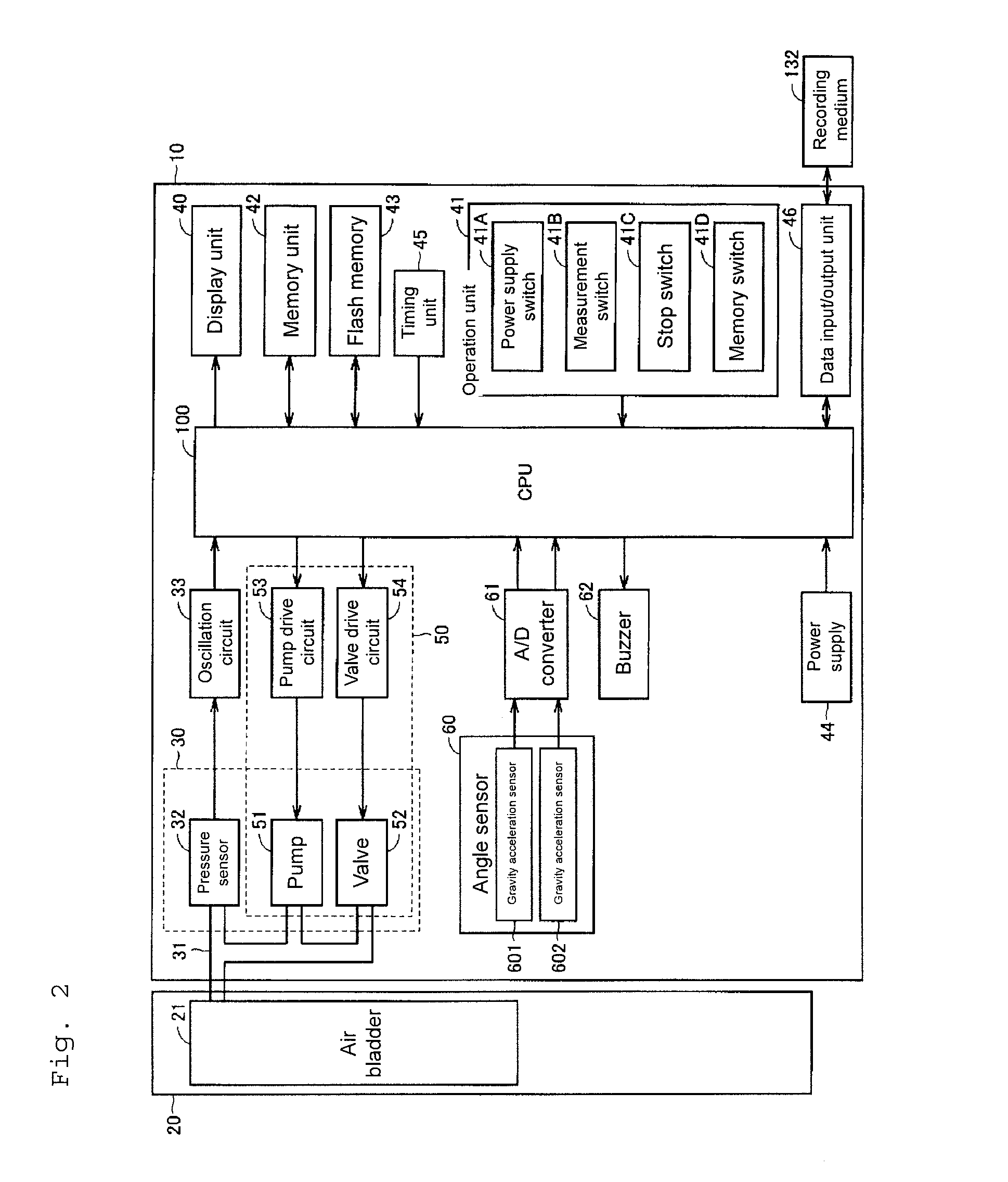
[0028]Embodiments of the present invention will be described with reference to the drawings. Identical reference numerals are given to identical and corresponding portions in the drawings, and description thereof will not be repeated.

[0029]First, a description will be given of an external view and a configuration of an electronic sphygmomanometer (hereinafter referred to as “sphygmomanometer”) according to one or more embodiments of the present invention.

(External View)

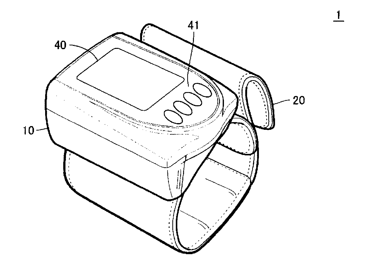
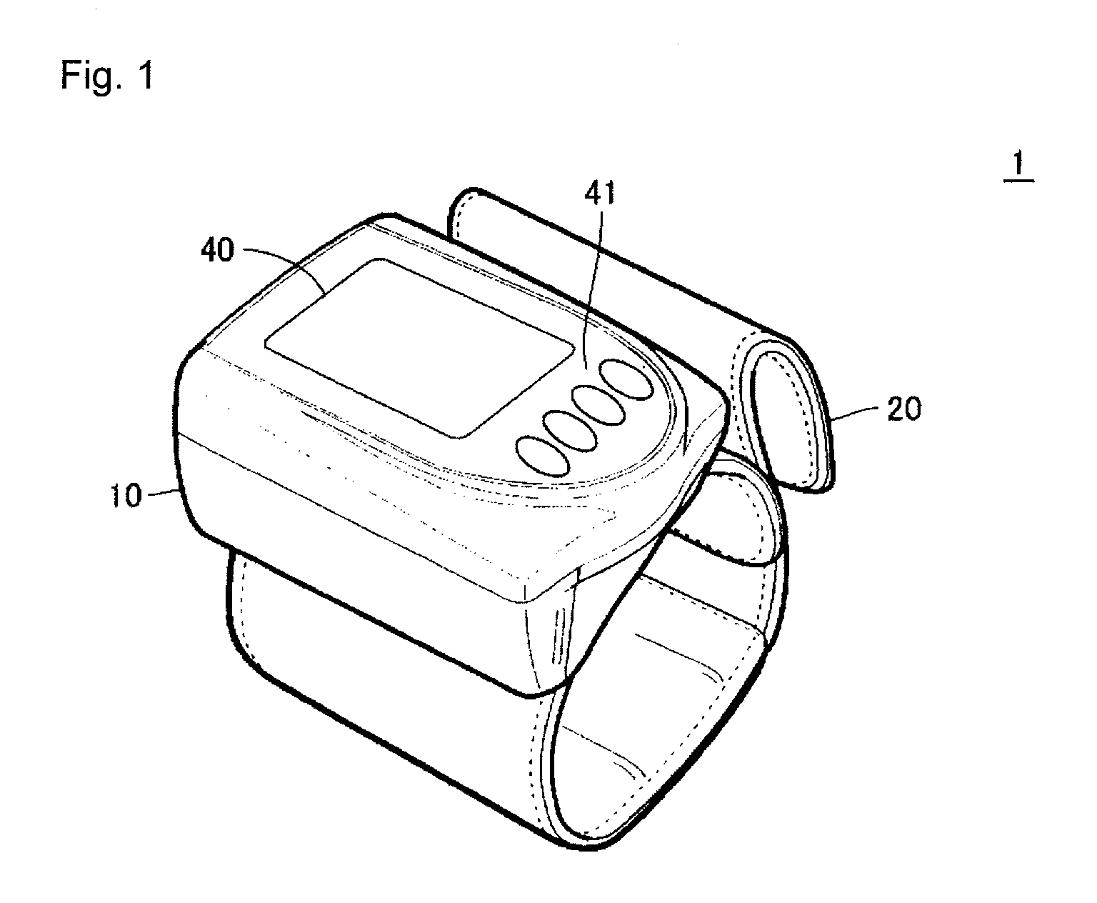
[0030]FIG. 1 is an external perspective view of a sphygmomanometer 1 according to one or more embodiments of the present invention.

[0031]As shown in FIG. 1, the sphygmomanometer 1 is equipped with a main body portion 10 and a cuff 20 that can be wound around a wrist of a person to be measured. The main body portion 10 is attached to the cuff 20. On a surface of the main body portion 10, a display unit 40 comprised of a liquid crystal display, for example, and an operation unit 41 configured to receive instructions fro...


PUM


Abstract

An electronic sphygmomanometer includes a pressure control unit configured to conduct pressurization control on a cuff (pressure control toward a specific direction) and acquire a cuff pressure signal at a time of the pressurization control to thereby measure a pressure pulse wave; a displacement decision unit configured to decide whether displacement has occurred between a position of the cuff and a virtual position of the heart based on an output from an angle sensor when the pressurization control is being conducted; and a return processing unit configured to, when it is decided that displacement has occurred, stop the pressurization control and conduct depressurization control on the cuff to thereby return an intra-cuff pressure to a specific pressure value that denotes a pressure value before the occurrence of the displacement. The pressure control unit resumes the pressurization control after processing by the return processing unit.

Description

TECHNICAL FIELD[0001]The present invention relates to an electronic sphygmomanometer and, more specifically to, an electronic sphygmomanometer equipped with an angle sensor.BACKGROUND ART[0002]An electronic sphygmomanometer for measuring a blood pressure based on arterial blood pressure information of an upper arm, a wrist, and a finger has been widely used. Values of the blood pressure tend to be determined lower if a measurement site is higher than the heart and determined higher if the measurement site is lower than the heart in position. Therefore, it is necessary to measure the blood pressure in a condition where the height of the measurement site agrees with that of the heart. Disagreement in height between the measurement site and the heart has been a major factor of fluctuations against management of daily changes in blood pressure value.[0003]Accordingly, a proposal has conventionally been made to measure the blood pressure in a condition where the height of the measurement...

Claims


Application Information

Patent Timeline
Patent Type & Authority Applications(United States)
IPC IPC(8): A61B5/0225
CPCA61B5/02225A61B2560/0261A61B5/0225A61B5/02233
Inventor KAWANO, ATSUSHISAWANOI, YUKIYA
Owner OMRON HEALTHCARE CO LTD
Why Eureka
Try Eureka