Fill level measuring device

Active Publication Date: 2014-12-04
IMF ELECTRONIC GMBH
View PDF3 Cites 5 Cited by
  • Summary
  • Abstract
  • Description
  • Claims
  • Application Information

AI Technical Summary

Benefits of technology

The patent discusses a device that measures the level of a liquid by measuring its temperature. At high frequencies, the device is able to maintain its accuracy even when the temperature changes. The technical effect of this patent is to provide a reliable and accurate way to measure the level of a liquid even at high operating frequencies.

Problems solved by technology

Because of the control unit consisting of semiconductor components their permanent operating temperature is limited to 85° C., which in many cases is not sufficient.
Since these devices, however, operate at very high frequencies, in a range definitely above 100 MHz, their resonance behavior noticeably worsens, and also their measurement accuracy despite the screened connecting lines.
Because of the voltage drop on the comparatively long lines and their susceptibility to interference, the circuit is inexact and not suited for high frequencies in the range above 10 MHz.
Its manufacture is, however, expensive and fault-prone.
The generation of a reference signal is difficult.

Method used


Image

  • Fill level measuring device
  • Fill level measuring device

Examples


Embodiment Construction

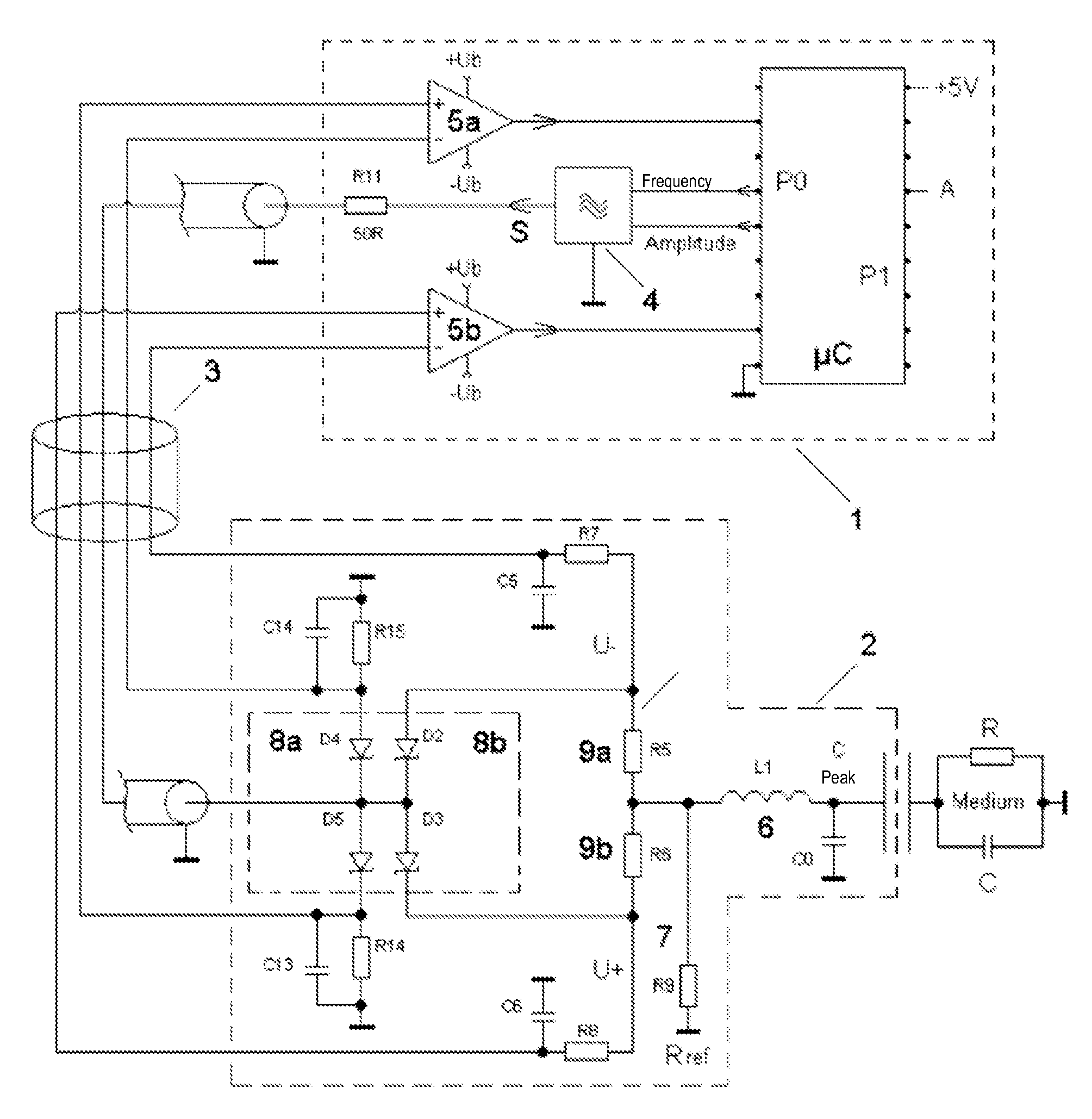
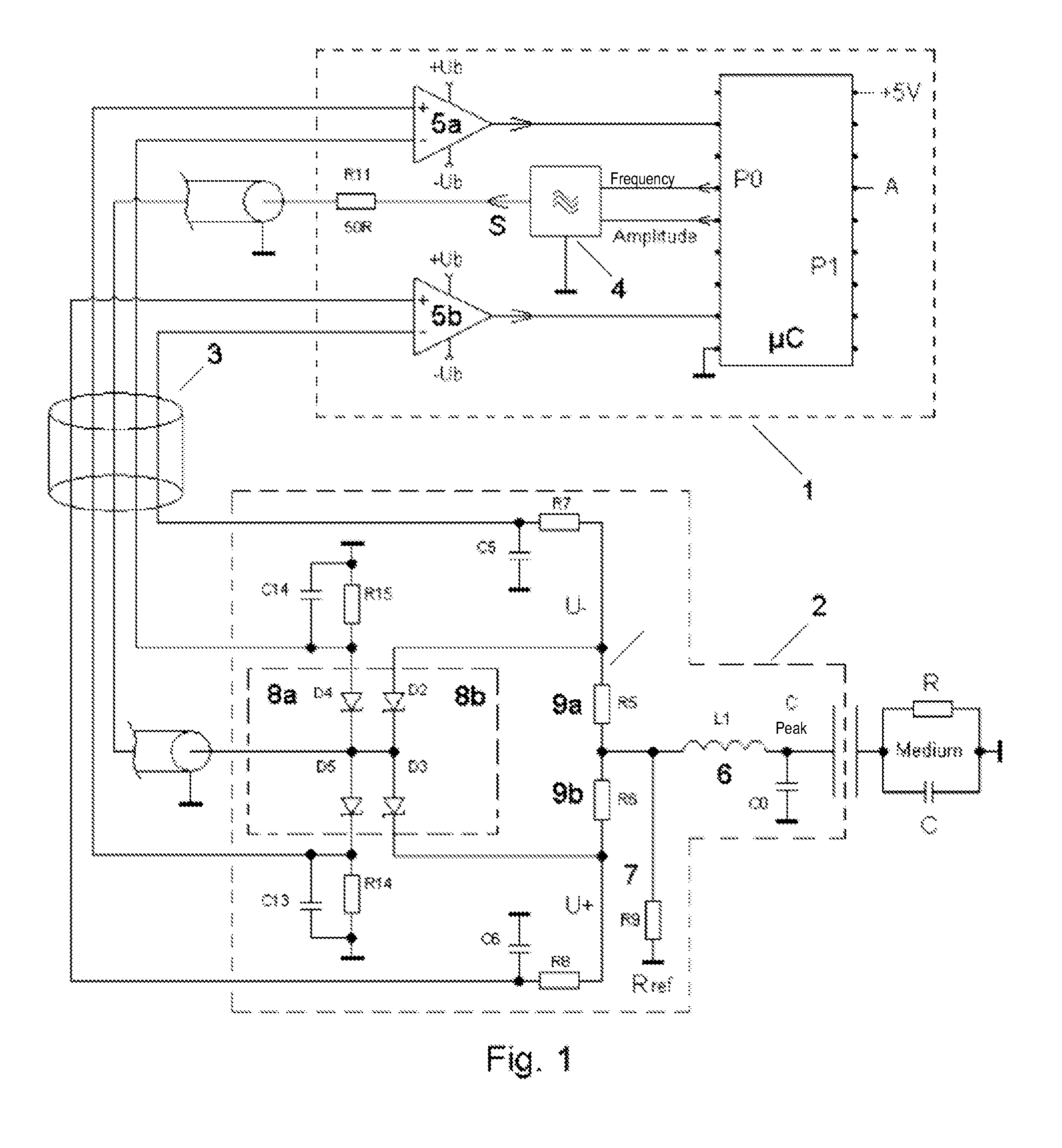
[0018]FIG. 1 shows an inventive fill level measuring device. The control unit 1 contains a micro-controller μC as an evaluation unit, as well as a high frequency generator 4, here a tunable sinus oscillator, as well as a first measurement amplifier 5a and a second measurement amplifier 5b. The control unit 1 is connected to a probe 2 via a partially screened connection line 3. The probe 2 has a measuring impedance 6. This contains an inductance L1 of several 100 nH. The parasitic capacitance of the housing is designated with C0 and is of several pF. It can be increased for tuning purposes. The capacitance of the medium is of the same order of magnitude. The resistance RMedium and the capacitance CMedium represent the impedance of the medium to be measured. The reference impedance 4 consists of an ohmic resistance thermally coupled with the probe 2 but preferentially not influenced by the medium.

[0019]The probe 2 also contains a first peak value rectifier 8a to acquire the transmissi...


PUM


Abstract

Fill level measuring device having a control unit, which contains a high-frequency generator for generating a transmission signal, an amplifier, an amplifier and an evaluation unit, and a spatially remote probe, which contains a measuring impedance, a reference impedance, a first rectifier and a second rectifier, as well as a connecting line between the control unit and the probe, wherein the rectifier detects the voltage of the transmission signal in the probe, and this voltage is transmitted to the control unit as a first DC voltage signal, and the rectifier converts the probe current in the probe into a second DC voltage signal via measuring resistors, and both signals are supplied to the control unit for the purpose of determining the fill level, wherein the rectifiers are thermally coupled to one another.

Description

CROSS-REFERENCE TO RELATED APPLICATIONS[0001]This application claims priority to PCT Application No. PCT / EP2013 / 051446, having a filing date of Jan. 25, 2013, based off of DE Application No. 102012201226.5 having a filing date of Jan. 27, 2012, the entire contents of which are hereby incorporated by reference.FIELD OF TECHNOLOGY[0002]The following relates to a fill level measuring device to determine the fill level of a medium in a container.BACKGROUND[0003]Capacitive fill level sensors have been used for a long time both as limit switches as well as for media determination. Their basic advantages are that they feature no mechanical moving parts and can measure “through” a housing wall consisting of an electrically insulating material, i.e. sealing problems are avoidable.[0004]Electronic fill level sensors for water-based media have been produced and marketed by the applicant under the designation LMT100, and those for oils and fats under the designation LMT110.[0005]DE102008027921B...

Claims


Application Information

Patent Timeline
IPC IPC(8): G01F23/00G01F23/26G01F25/00
CPCG01F23/0084G01F23/266G01F25/00G01F23/265G01F23/806
Inventor HOCH, WERNER
Owner IMF ELECTRONIC GMBH
Why Eureka
Try Eureka