Guidewire

a technology of guidewires and wires, applied in the direction of guide wires, catheters, diagnostic recording/measuring, etc., can solve the problem of impaired flexibility of the tip portion of the guidewir

Inactive Publication Date: 2011-10-06
ASAHI INTECC CO LTD
View PDF2 Cites 4 Cited by
  • Summary
  • Abstract
  • Description
  • Claims
  • Application Information

AI Technical Summary

Benefits of technology

[0007]The present invention has been made to solve the foregoing technical problems, and an object of the present invention is to provide a guidewire in which

Problems solved by technology

In this case, flexibility of the tip portion of the guidewire is impaired, and thus th

Method used


Image

  • Guidewire
  • Guidewire
  • Guidewire

Examples


first embodiment

[0023]Hereinafter, the guidewire according to the present invention will be described with reference to FIGS. 1 and 2.

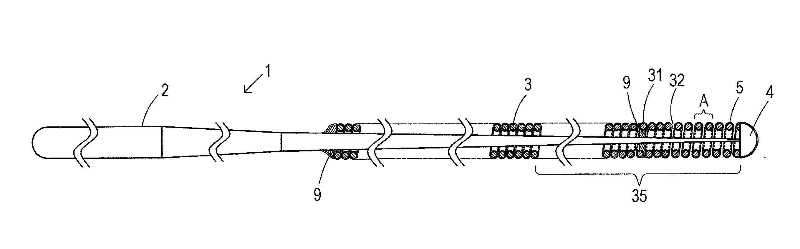
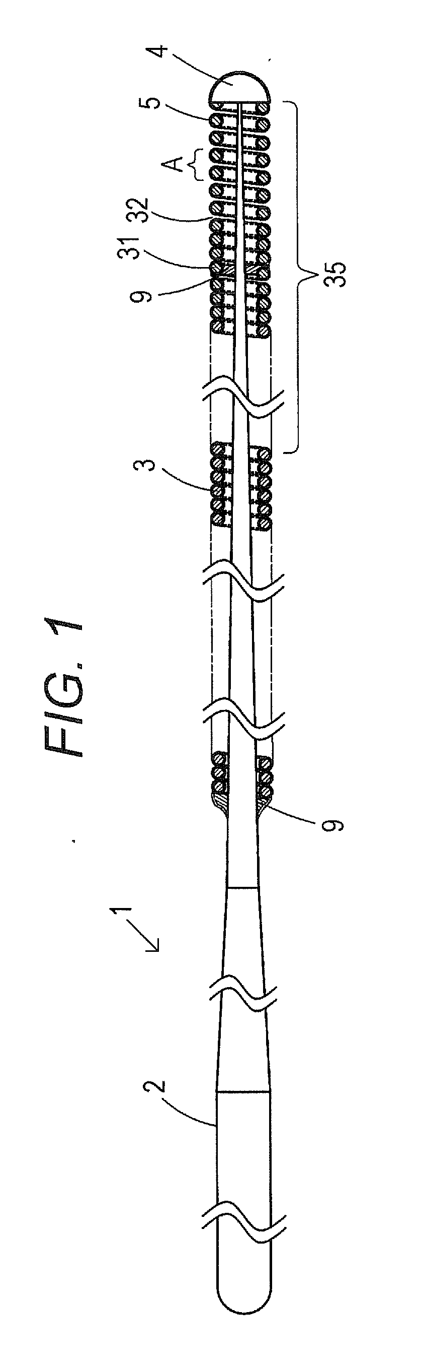
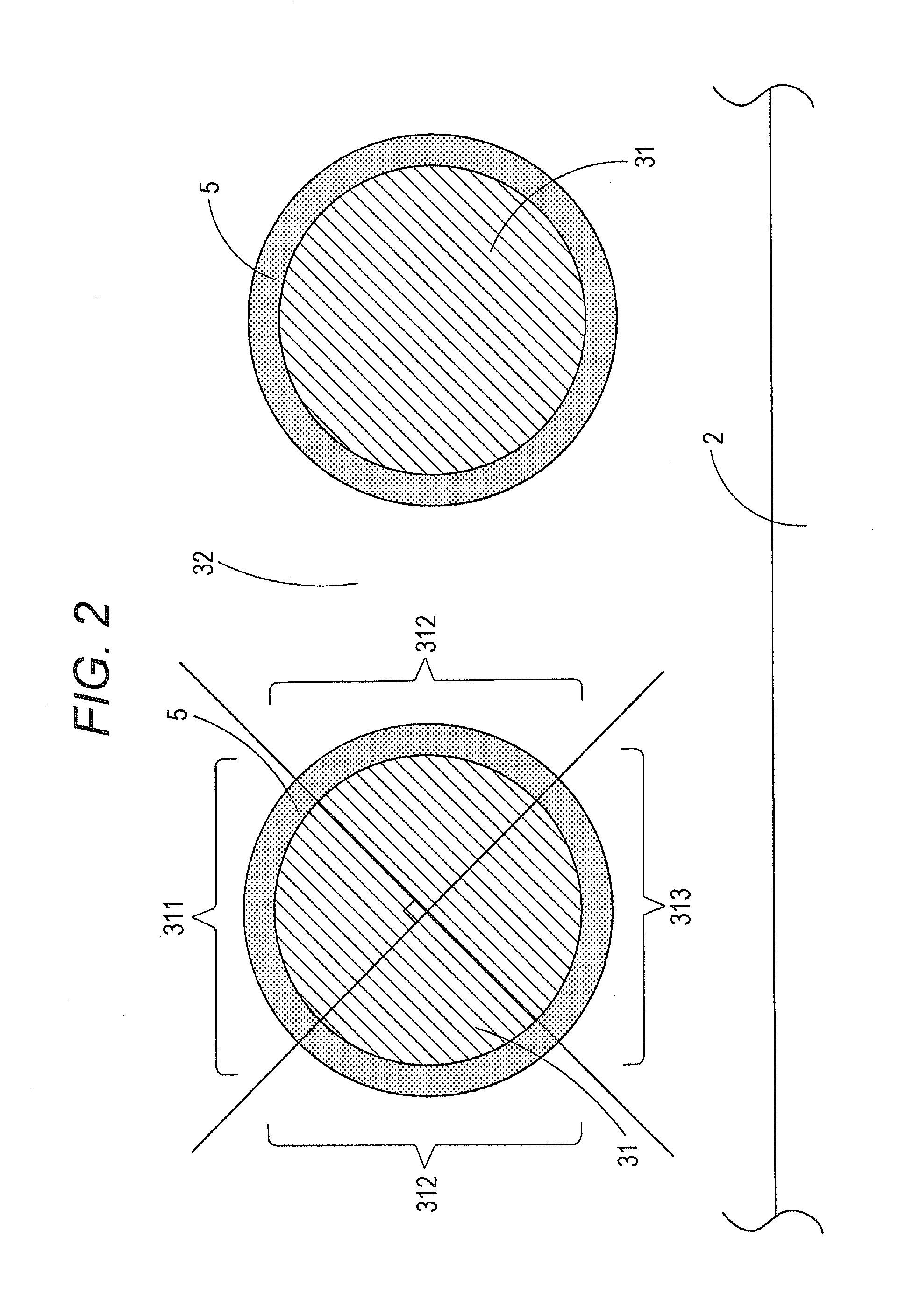
[0024]FIG. 1 is a vertical cross-sectional view showing a guidewire according to an embodiment of the present invention. FIG. 2 is a partially enlarged view of the part A shown in FIG. 1.

[0025]It is to be noted that, in FIG. 1, the left side is referred to as “a proximal side,” and the right side is referred to as “a front side” for convenience of explanation.

[0026]Also, in FIG. 1, the guidewire is shortened in the longitudinal direction to show the entirety schematically for ease of understanding. Accordingly, the scale ratio of the entire guidewire differs from the actual one.

[0027]In FIG. 1, a guidewire 1 has a core shaft 2 tapered toward the front end and a coiled body 3 covering the tip portion of the core shaft 2. The front end of the core shaft 2 and the front end of the coiled body 3 are fixed at a most distal portion 4. Also, the core shaft 2 and the coiled ...

second embodiment

[0056]In the guidewire of the second embodiment, the hydrophilic coating agent 15 is protruded in the direction of the outward surface portion 311. In such a shape, the coating thickness of the hydrophilic coating agent 15 is increased at the outward surface portion 311. Accordingly, since hydrophilicity is given to the guidewire for a long period, durability of lubricity of the guidewire 1 can be improved.

[0057]Also, since the thickness of the hydrophilic coating agent 15 coating the inward surface portion 313 is small, a space between the core shaft and the coiled body 3 can be secured sufficiently. Accordingly, flexibility of the coiled body 3 can be further improved.

[0058]Such a shape of the hydrophilic coating agent 15 can be formed by the following method, for example.

[0059]Before coating the coils of strand 31 with the hydrophilic coating agent 15, to heighten affinity of the coils of strand 31 for the hydrophilic coating agent 15, it is preferable to irradiate the outer circ...


PUM

PropertyMeasurementUnit
Thicknessaaaaaaaaaa
Hydrophilicityaaaaaaaaaa

Abstract

An object of the present invention is to provide a guidewire in which the movement of coils of strand is not inhibited by a hydrophilic coating agent, and flexibility of a coiled body is secured even in a case where its coiled body is coated with the hydrophilic coating agent. The guidewire includes a core shaft, a coiled body including coils of strand wound around an outer circumference of the core shaft, and a hydrophilic coating agent coating at least a part of the coiled body. At least the part of the coiled body is coated with the hydrophilic coating agent so that a gap may be formed between the coils of strand.

Description

CROSS REFERENCE TO RELATED APPLICATIONS[0001]This application is based on Japanese Patent Application No. 2010-080081 filed with the Japan Patent Office on Mar. 31, 2010, the entire content of which is hereby incorporated by reference.TECHNICAL FIELD[0002]The present invention relates to a guidewire forming a lubricating surface.BACKGROUND ART[0003]Conventionally, as for a guidewire that guides a catheter or the like used by being inserted in a tubular organ such as a vessel, a digestive tract, or a ureter or an intracorporeal tissue for treatment or examination, several kinds each provided on its surface with a hydrophilic coating agent to reduce a friction with the intracorporeal tissue are proposed.[0004]For example, in a medical instrument described in Japanese Patent Application Laid-Open No. 2004-215710, a lubricating coat 7 (a hydrophilic coating agent) is provided at the outer circumference of the entire instrument including a metal-made core wire 4 and coils (a first coil 5...

Claims


Application Information

Patent Timeline
IPC IPC(8): A61M25/09
CPCA61L31/10A61L31/14A61L2400/10A61M2025/09133A61M25/09A61M2025/09083
Inventor SATOZAKI, JUNJI
Owner ASAHI INTECC CO LTD
Why Eureka
Try Eureka