
Splint for treatment of musculoskeletal injury of the hand

a musculoskeletal injury and hand technology, applied in the field of splints, can solve the problems of low recovery rate, significant functional limitations and pain, and none generally having very good patient outcomes, and achieve the effects of increasing the range of motion of the pip joint, restoring the force of the finger, and encouraging higher adherence rates

Inactive Publication Date: 2011-10-06
U S GOVERNMENT REPRESENTED BY THE DEPT OF VETERANS AFFAIRS
View PDF3 Cites 10 Cited by
  • Summary
  • Abstract
  • Description
  • Claims
  • Application Information

AI Technical Summary

Benefits of technology

The invention is a new splint design that improves the range of motion and adherence of the fingers. It has several technical effects. First, it has cavities for bats that can be inserted after the splint is donned, allowing for adjustable restoring force and reducing pain. Second, it is made of low-friction material, comfortable to wear and can be easily rolled onto the finger. Third, it provides a stable and flexible torque to the joint, promoting healing and reducing pain. Fourth, it is comfortable and held in place by circumferential tension with the pressure diffused over the whole finger. Fifth, it allows for visual monitoring of skin health and circulation, and preserves function in the hand. Lastly, it is easy to don and doff, and can be used for treatment of joint contracture.

Problems solved by technology

Contracture of a proximal interphalangeal (PIP) joint of a hand can cause significant functional limitations and pain.
Even with surgery and aggressive splinting, the rate of recovery is low.
There are many different types of known splints for PIP contracture, with none generally having very good patient outcomes.
Because of the small size of the joint, splints tend to be bulky and oversized.
This can increase the functional limitations of the user because the splints can be more cumbersome than the un-splinted affected fingers.
Additionally, many of the splints do not adequately distribute load intended to extend the joint, which results in high-pressure points across the finger, which can lead to skin breakdown, pain and discomfort.
To be effective, a splint must be worn for many hours each day, but this can present serious risks for circulation and skin health.
Bulky splints can be difficult to fit and improper fit can diminish effectiveness and lead to complications.
The splints are also difficult to keep in place and often roll and slip around the finger.
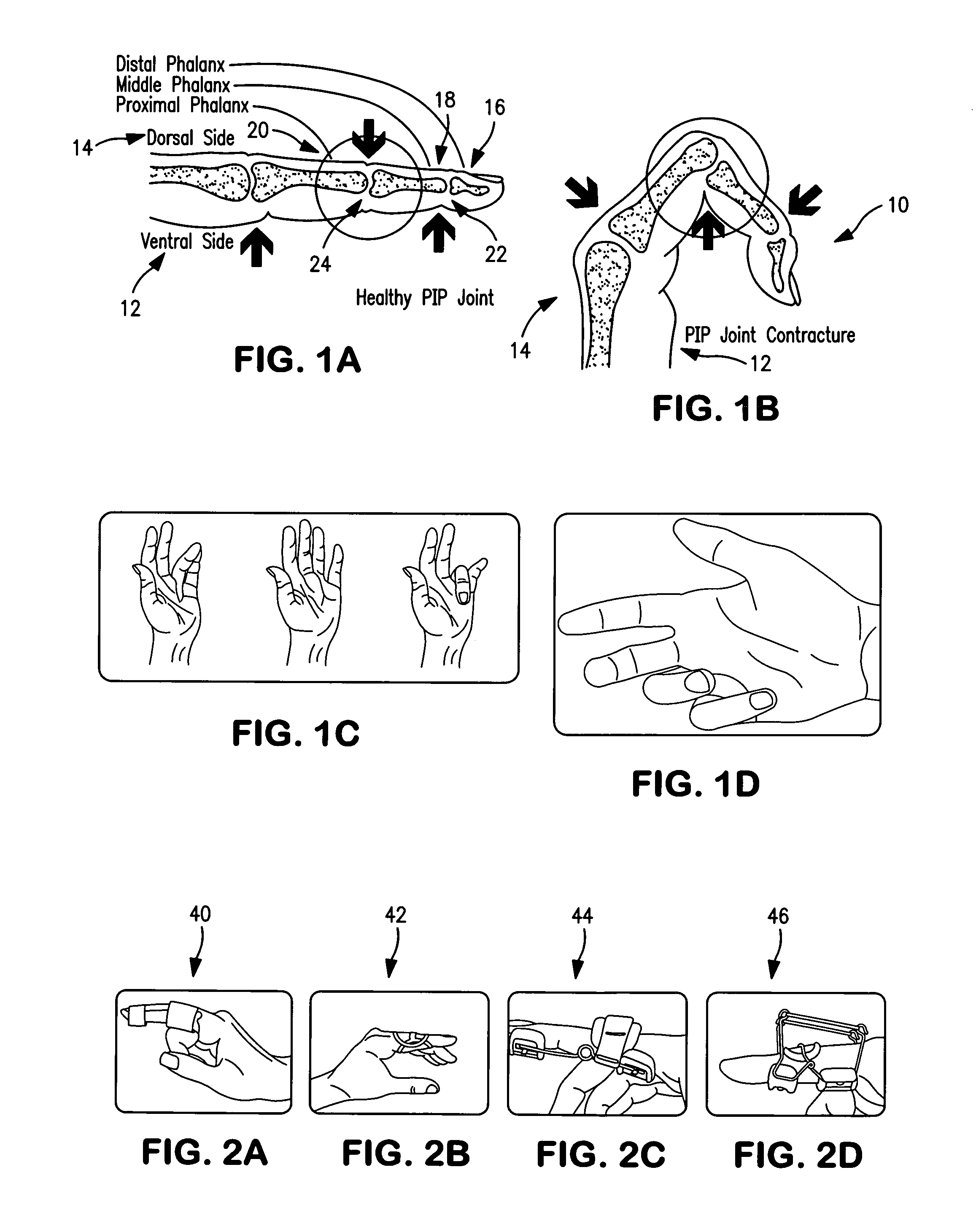
Oval-8-splint design 42 of FIG. 2B can be difficult to put on, and can put damaging pressure in very small sensitive areas.
Further, the Bunnel splint design 44 of FIG. 2C may not provide enough corrective force, and can be bulky and roll around a user's finger, and the R. Knuckle bender splint design 46 of FIG. 2D can be cumbersome in nature from use and functionality standpoints.
There are currently no splints available that adequately straighten the joint without health complications even when the patient adheres to the treatment.
Because of the same problems that cause health complications and functional limitation, therapists also see low rates of adherence to known regimens.
Moreover, even an otherwise very effective splint is only effective if it is worn regularly.
In an exemplary known splint design, U.S. Pat. No. 5,095,897 discloses a neoprene splint which is relative low-profile, but the method of fabrication thereof results in a seam, which protrudes from the finger.
While some existing splint designs do not have such a seam, they are nevertheless of some standard tubular or tapered form and are not designed to mimic exactly the shape of the joint that is being addressed.

Method used


Image

  • Splint for treatment of musculoskeletal injury of the hand
  • Splint for treatment of musculoskeletal injury of the hand
  • Splint for treatment of musculoskeletal injury of the hand

Examples


Embodiment Construction

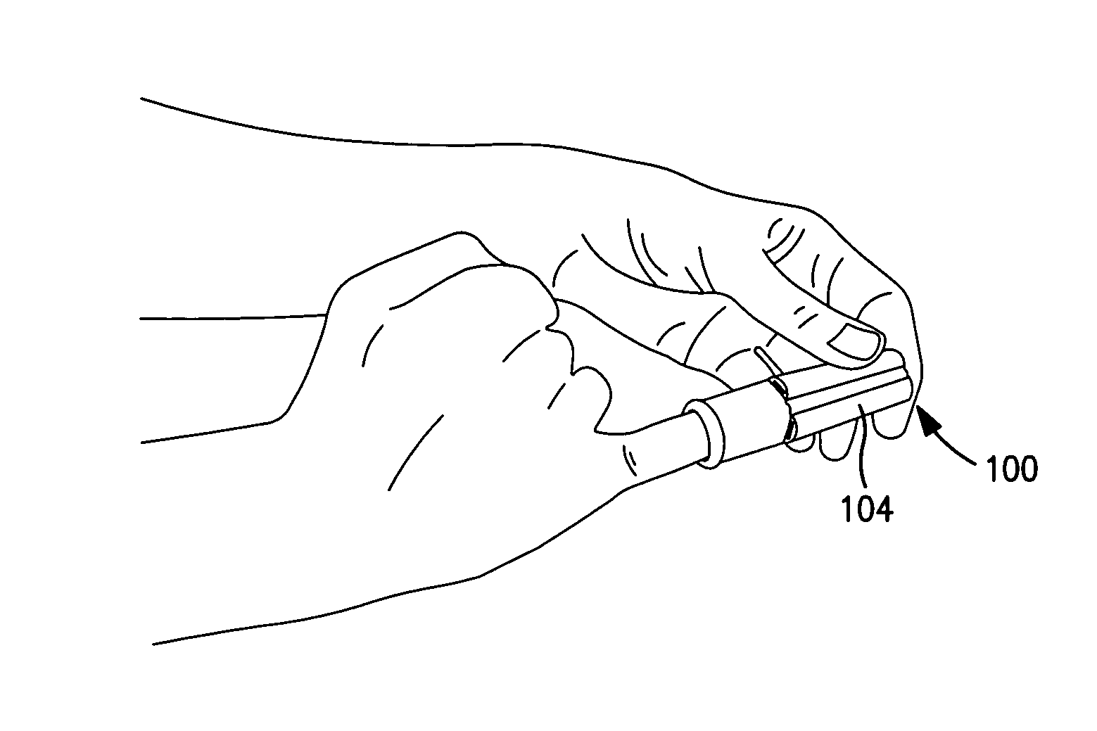
[0027]Referring now to the drawings wherein like reference numerals designate corresponding parts throughout the several views, FIGS. 3A-11 are views illustrative of splints according to the invention for treatment of musculoskeletal injury of a hand, and manufacturing and use methods thereof.

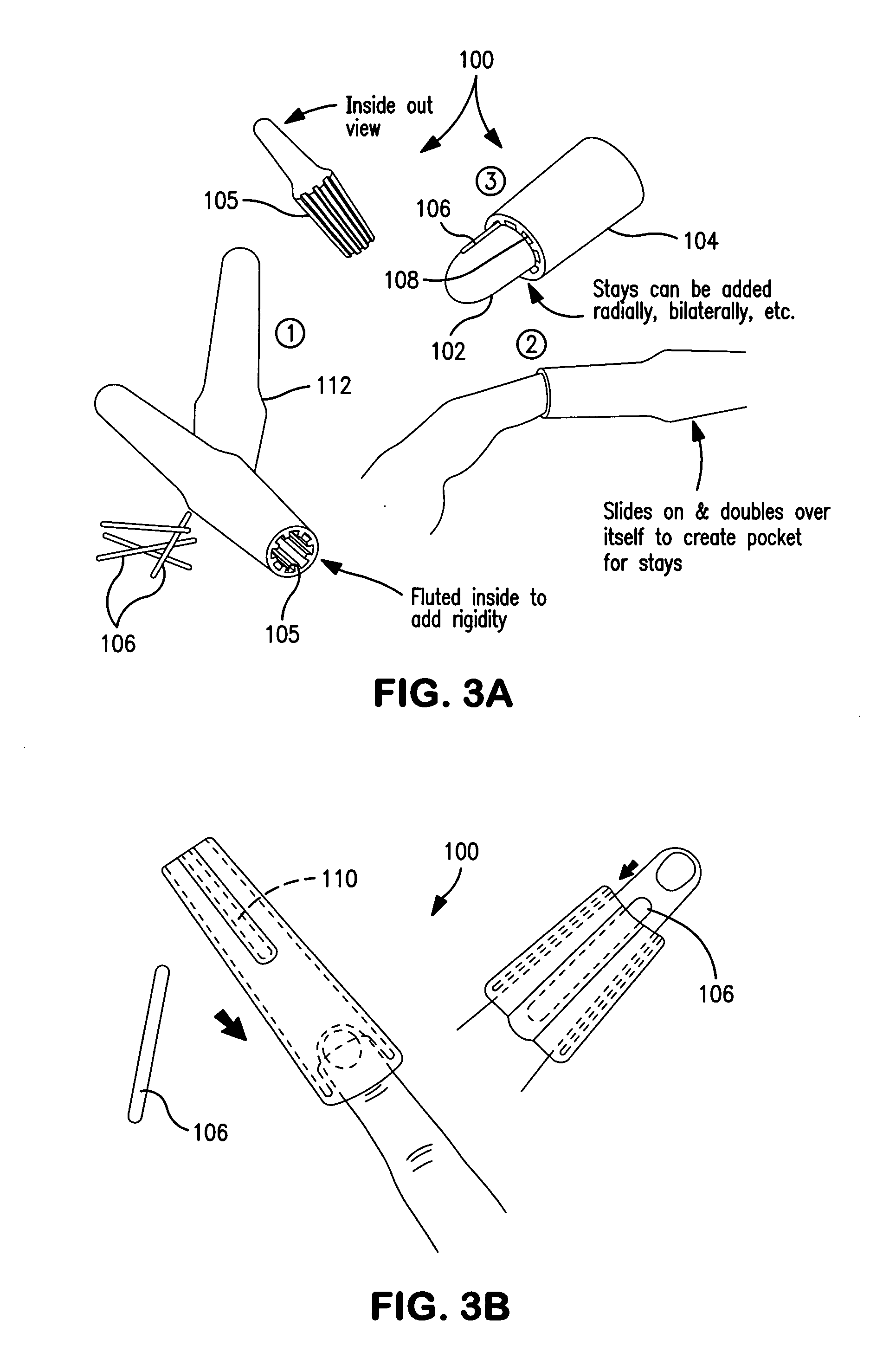
[0028]Referring to FIGS. 3A-3D, according to an embodiment of the invention, a splint 100 is generally formed of a soft rubber sleeve which may double over itself easily when the finger is inserted so as to alleviate the strain of trying to stretch or roll the splint over the affected joint. Splint 100 may generally include first and second portions forming inner and outer splint layers 102, 104, with outer layer 104 being fluted at 105 in a generally longitudinal direction for adding rigidity to the splint. Additional rigidity may be added by means of stays 106 (e.g. battens) insertable in cavities 108 formed between inner and outer layers 102, 104 for the FIG. 3A embodiment, and within pre-fo...


PUM


Abstract

A splint for treatment of a joint including a generally longitudinal body including first and second portions forming inner and outer splint layers, with the second portion being rollable onto the first portion to form the splint. The outer splint layer may include a longitudinal cavity for insertion of a stay, and / or may include a fluted section for permitting insertion of a stay between the inner and outer splint layers. The longitudinal body may be linear or curved. The first and second portions may include areas having different thicknesses for adding rigidity to the splint structure at a predetermined location. The splint may include a cutout for exposing a predetermined portion of a user's finger. The splint may be made of a flexible material such as rubber, silicone and / or urethane. The splint may include a reduced friction surface layer for minimizing sticking of the splint during donning.

Description

CROSS-REFERENCE TO RELATED APPLICATION[0001]This application is based on U.S. Provisional Application Ser. No. 61 / 306,656, filed Feb. 22, 2010, the priority of which is hereby claimed. The contents of this priority application are incorporated herein by reference.BACKGROUND OF INVENTION[0002]a. Field of Invention[0003]The invention relates generally to splints and other such devices, and more particularly, to a splint for treatment of musculoskeletal injury of a hand by, for example, providing a stabilizing and / or a flexing torque to a joint of a human finger.[0004]b. Description of Related Art[0005]Contracture of a proximal interphalangeal (PIP) joint of a hand can cause significant functional limitations and pain. Referring to FIGS. 1A-1D, contracture of a PIP joint is illustrated in a human finger 10 which includes vertical and dorsal sides 12, 14, distal, middle and proximal phalanxes 16, 18, 20, and interphalangeal (PIP) joints 22, 24, 26 between the phalanxes. Dupuytren's dise...

Claims


Application Information

Patent Timeline
Patent Type & Authority Applications(United States)
IPC IPC(8): A61F5/00
CPCA61F5/05875A61F2005/0197A61F5/10
Inventor WOLLSTEIN, RONITOGDEN, THOMASPEARLMAN, JONATHANCOOPER, RORY A.WHITE, DAVIDZISOOK, MIRIAM
Owner U S GOVERNMENT REPRESENTED BY THE DEPT OF VETERANS AFFAIRS
Learn More