
Implantable Prosthesis With Depot Retention Feature

a technology of implantable prostheses and depots, applied in the field of implantable prostheses, can solve the problems of embolic hazards, difficult application of uniform coatings with good adhesion to substrates,

Inactive Publication Date: 2011-10-06
ABBOTT CARDIOVASCULAR
View PDF24 Cites 36 Cited by
  • Summary
  • Abstract
  • Description
  • Claims
  • Application Information

AI Technical Summary

Benefits of technology

[0011]In aspects of the present invention, a method of making an implantable, intraluminal prosthesis comprises forming a tubular frame of interconnected structural members, forming through-holes in the structural members, and forming an indentation in an inner surface of each of the through-holes. The method further comprises forming a bioabsorbable depot in each of the through-holes, which comprises forming a protrusion of the bioabsorbable depot that engages the indentation of the through-hole in which the bioabsorbable depot is retained. Engagement of the protrusion with the indentation prevents the bioabsorbable depot from sliding out of the through-hole.

Problems solved by technology

Problems with PTCA include formation of intimal flaps or torn arterial linings, both of which can create another occlusion in the lumen of the coronary artery.
Moreover, thrombosis and restenosis may occur several months after the procedure and create a need for additional angioplasty or a surgical bypass operation.
The application of a uniform coating with good adhesion to a substrate can be difficult for small and intricate medical devices, such as certain stents for coronary and peripheral arteries.
Depending on their size, the drug-containing compositions may cause an embolic hazard if they dislodge as particles from the stent and flow into a patient's blood stream.

Method used


Image

  • Implantable Prosthesis With Depot Retention Feature
  • Implantable Prosthesis With Depot Retention Feature
  • Implantable Prosthesis With Depot Retention Feature

Examples


Embodiment Construction

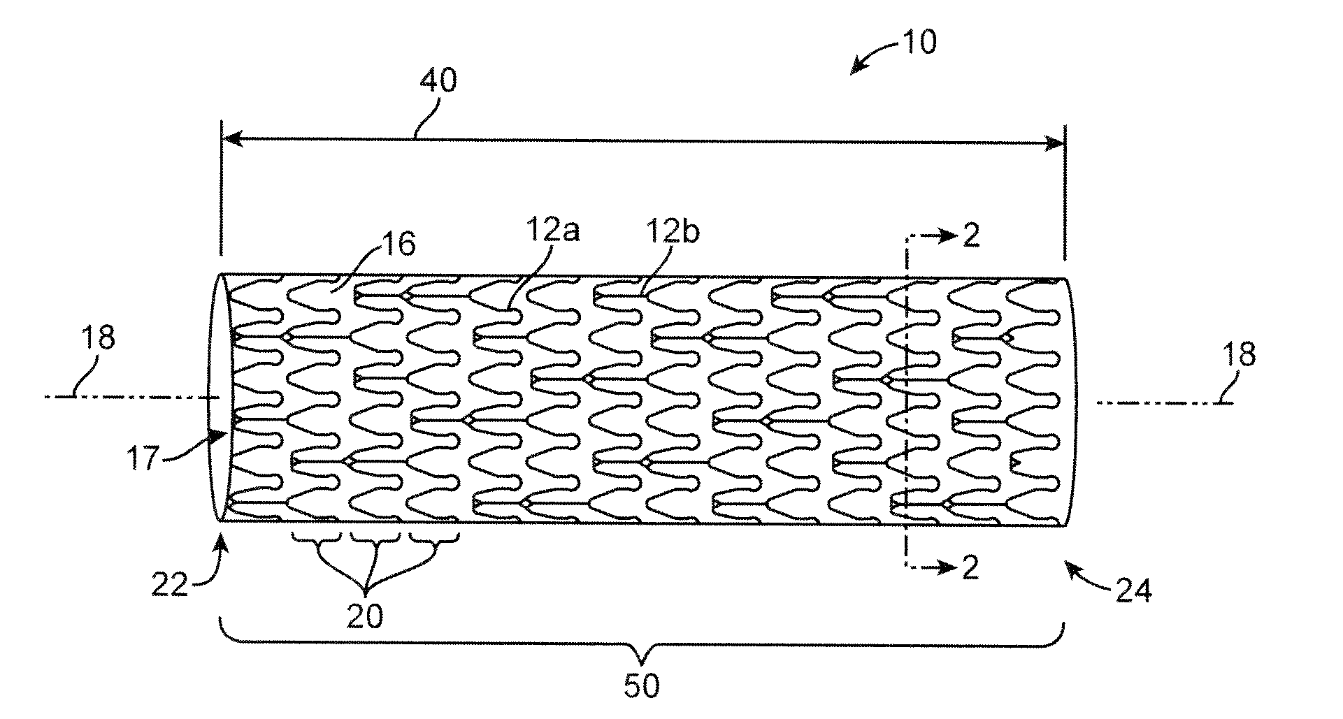
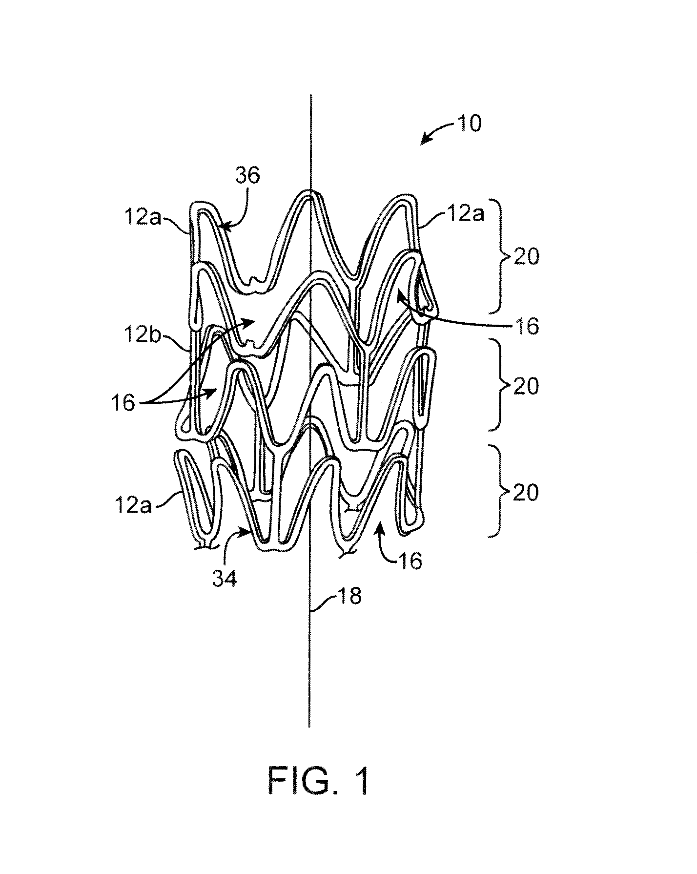
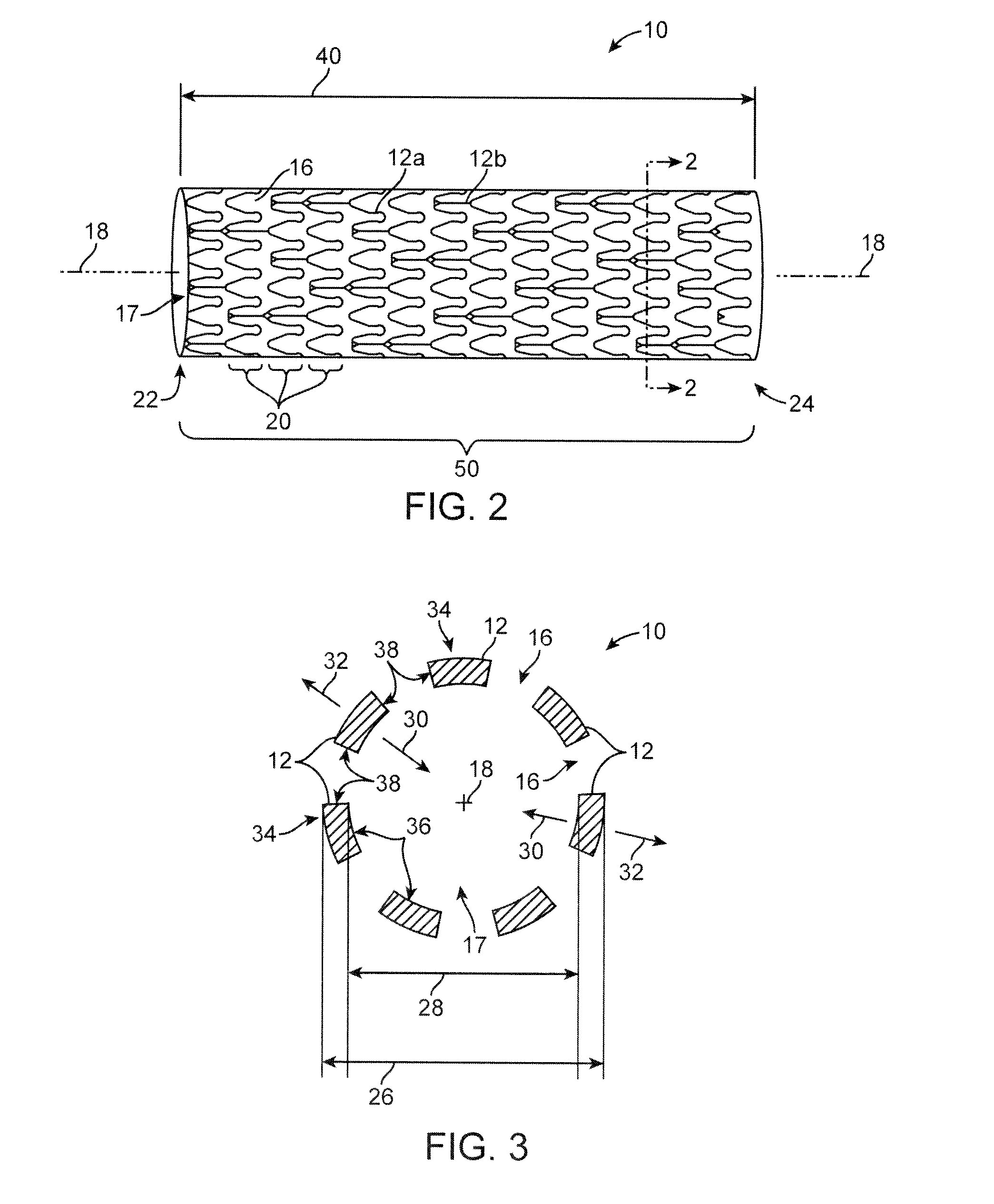
[0031]Referring now in more detail to the exemplary drawings for purposes of illustrating embodiments of the invention, wherein like reference numerals designate corresponding or like elements among the several views, there is shown in FIG. 1 an upper portion of a stent 10 having an overall body shape that is hollow and tubular. The stent can be balloon expandable or self-expandable.

[0032]The present invention encompasses stents having any particular geometrical configuration, such as a zig-zag, sinusoidal or serpentine strut configuration, and should not be limited to the patterns illustrated herein. The variation in stent patterns is virtually unlimited.

[0033]FIGS. 1 and 2 show stents with two different stent patterns. The stents are illustrated in an uncrimped or expanded state. In both FIGS. 1 and 2 the stent 10 includes many interconnecting struts 12a, 12b separated from each other by gaps 16. The struts 12a, 12b form a tubular frame and can be made of any suitable material, su...


PUM

PropertyMeasurementUnit
Lengthaaaaaaaaaa
Angleaaaaaaaaaa
Volumeaaaaaaaaaa

Abstract

A prosthesis for intraluminal drug delivery can comprise a plurality of interconnected struts that form a tubular scaffold structure. The struts include through-holes with an inner surface configured to retain a bioabsorbable depot. The bioabsorbable depot includes a drug-polymer composition that hydrolytically degrades upon implantation. The inner surface of the through-hole can be an entirely smooth and continuous area that is concave or convex, with no geometric discontinuities. The inner surface of the through-hole can include any number of constricted and distended regions to form grooves of a size and shape carefully selected to engage a corresponding geometric feature of the bioabsorbable depot.

Description

FIELD OF THE INVENTION[0001]Briefly and in general terms, the present invention generally relates to an implantable prosthesis and, more particularly, to a drug eluting stent.BACKGROUND OF THE INVENTION[0002]In percutaneous transluminal coronary angioplasty (PTCA), a balloon catheter is inserted through a brachial or femoral artery, positioned across a coronary artery occlusion, and inflated to compress against atherosclerotic plaque to open, by remodeling, the lumen of the coronary artery. The balloon is then deflated and withdrawn. Problems with PTCA include formation of intimal flaps or torn arterial linings, both of which can create another occlusion in the lumen of the coronary artery. Moreover, thrombosis and restenosis may occur several months after the procedure and create a need for additional angioplasty or a surgical bypass operation. Stents are used to address these issues. Stents are small, intricate, implantable medical devices and are generally left implanted within t...

Claims


Application Information

Patent Timeline
IPC IPC(8): A61F2/82B23P11/00
CPCA61F2230/0013A61F2/915A61F2/91A61F2210/0004A61F2210/0076A61F2250/0068Y10T29/49826B33Y80/00
Inventor PACETTI, STEPHEN D.KERRIGAN, CAMERON K.
Owner ABBOTT CARDIOVASCULAR
Learn More