
Respirator

a technology of a respirator and a cylinder head, which is applied in the field of respirators, can solve the problems of low cost, complicated manufacturing of the u-shaped channel with the three holes arranged at right angles in relation to one another, and the loss of gas energy, etc., and achieve the effect of low cos

Inactive Publication Date: 2011-10-13
DRAGERWERK AG
View PDF5 Cites 0 Cited by
  • Summary
  • Abstract
  • Description
  • Claims
  • Application Information

AI Technical Summary

Benefits of technology

[0005]The object of the present invention is therefore to make available a respirator or anesthesia apparatus and a process for manufacturing a respirator or anesthesia apparatus, in which the volume flow of a gas can be measured with a means according to the differential pressure method and said means can be manufactured in a simple manner at a low cost.
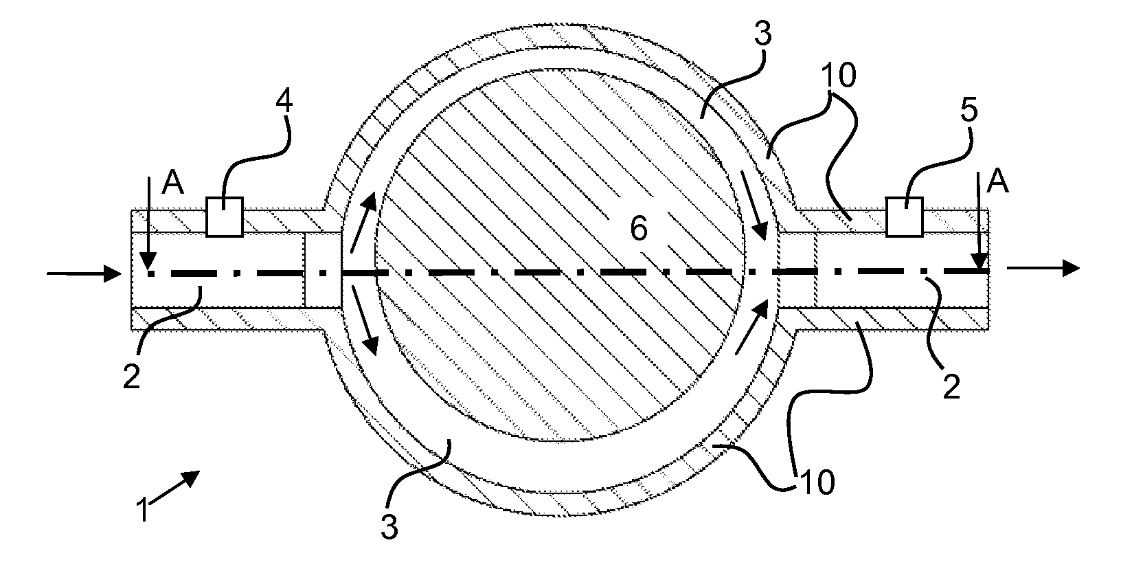
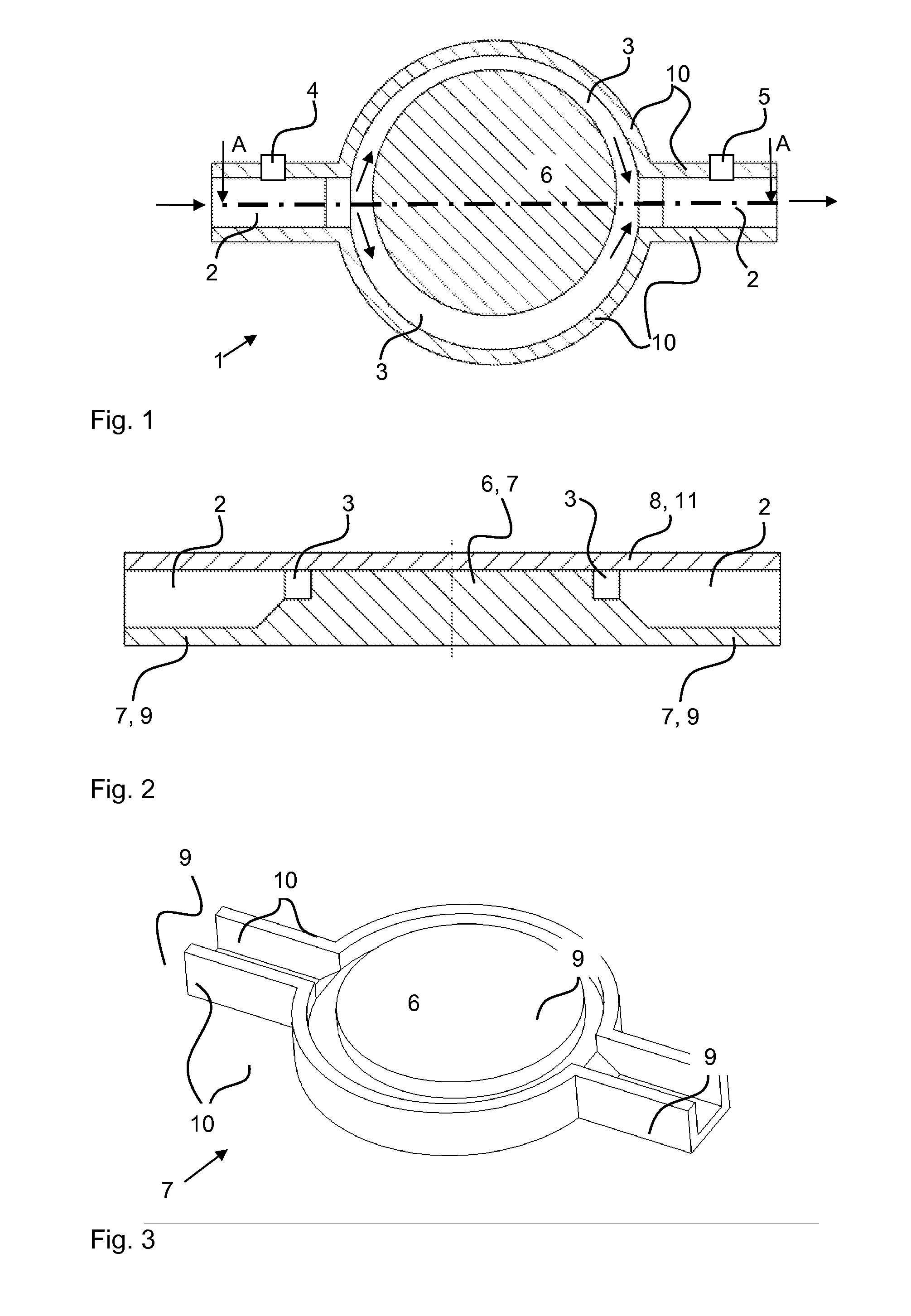
[0007]Due to the splitting of the gas to be measured between the first and second pressure-measuring points into at least two partial flows, which are sent through the at least two partial flow channels, the means or manufacture is especially simple and inexpensive.
[0011]The flow space with the essentially constant curvature of the at least two separate partial flow channels is preferably directed eccentrically in relation to the cylinder. Due to the eccentric arrangement, fluctuations of the flows between the two partial flow channels can be reduced or eliminated.
[0014]The flow channel, especially the at least two separate partial flow channels, are preferably manufactured from a thermoplastic plastic with a bottom part and a cover part. The flow channel, especially the at least two separate partial flow channels, can thus also be manufactured by means of injection molding in an especially simple manner and at a low cost.

Problems solved by technology

Increased friction, which leads to a loss of energy of the gas, which can be measured as a pressure drop, will develop in the cross section contraction due to the increased velocity.
The manufacture of the U-shaped channel with the three holes arranged at right angles in relation to one another is complicated by means of injection molding with an injection die because slides are necessary for this.
Narrow gaps can also be prepared with difficulty only by means of injection molding as a cross section contraction, e.g., as a diaphragm, because thin die structures, which are highly unstable, are to be prepared for this.
Long flow channels are also disadvantageous because of the large space required at a respirator or anesthesia apparatus.

Method used


Image

  • Respirator
  • Respirator

Examples


Embodiment Construction

[0029]Referring to the drawings in particular, a means for measuring the volume flow of a gas 1 is provided as part of a respirator 20. Such respirators are used for the artificial respiration of patients and anesthesia apparatuses are used, besides for respiration, also for the anesthesia of patients. FIG. 4 shows a respirator or anesthesia apparatus 20 having a breathing air circulation system, i.e., the expiration gas expired by the patient is reused for rebreathing as an inspiration gas. The breathing air is sent by a gas delivery means 22 through gas lines 24 in a breathing air circulation system 30. A first, inspiratory nonreturn valve 32 and a second, expiratory nonreturn valve 34 are arranged in the gas lines. An expiration gas line and an expiration gas tube 26 and an inspiration gas line and an inspiration gas tube 28 are formed as a result. A Y-piece 40, which sends the inspiration gas and the expiration gas to and from a patient to be respirated artificially, is connecte...


PUM

PropertyMeasurementUnit
Pressureaaaaaaaaaa
Flow rateaaaaaaaaaa
Thermoplasticityaaaaaaaaaa

Abstract

A respirator or anesthesia apparatus for the artificial respiration of a patient is provided with a gas delivery device, at least one gas line for forming a breathing air line system, at least one device for measuring a volume flow of a gas according to the differential pressure method with a flow channel, a first pressure-measuring point and a second pressure-measuring point. The second pressure-measuring point is arranged in the direction of flow of the gas to be measured after the first pressure-measuring point at the flow channel. Furthermore, the flow channel is split into at least two separate partial flow channels in the direction of flow of the gas to be measured between the first pressure-measuring point and the second pressure-measuring point.

Description

CROSS REFERENCE TO RELATED APPLICATIONS[0001]This application claims the benefit of priority under 35 U.S.C. §119 of German Patent Application DE 10 2010 014 873.3 filed Apr. 10, 2010, the entire contents of which are incorporated herein by reference.FIELD OF THE INVENTION[0002]The present invention pertains to a respirator (also known as a ventilator) and anesthesia apparatus for the artificial respiration (ventilation) of a patient, including a gas delivery means, at least one gas line for forming a breathing air line system, especially a breathing air circulation system and at least one means for measuring a volume flow of a gas according to a differential pressure method and to a process of manufacturing a respirator and anesthesia apparatus.BACKGROUND OF THE INVENTION[0003]Artificial respiration of patients is necessary for various medical applications, e.g., during surgery. Respirators are used for the artificial respiration of patients and can additionally also be used for an...

Claims


Application Information

Patent Timeline
IPC IPC(8): A61M16/01B29C65/00B29C45/00A61M16/00B23P17/04
CPCY10T29/4998A61M16/22Y10T29/49826A61M2016/003A61B5/091A61M16/00A61M16/104A61M16/01
Inventor SCHMID, UWEBRANDT, ANDREAS
Owner DRAGERWERK AG
Learn More