Collapsible Recumbent Tricycle

a recumbent tricycle and seat technology, applied in the field of small land vehicles, can solve the problems of losing aerodynamic advantage, unable to fit through gates and other narrow places, and collapse to a small size, and achieve the effect of easy collapse and quick and easy collaps

Active Publication Date: 2011-10-13
BALL ALAN ROY +1
View PDF4 Cites 28 Cited by
  • Summary
  • Abstract
  • Description
  • Claims
  • Application Information

AI Technical Summary

Benefits of technology

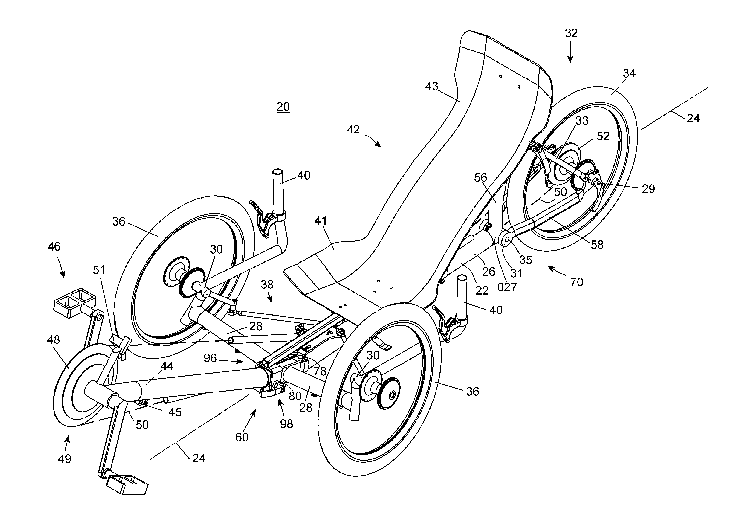
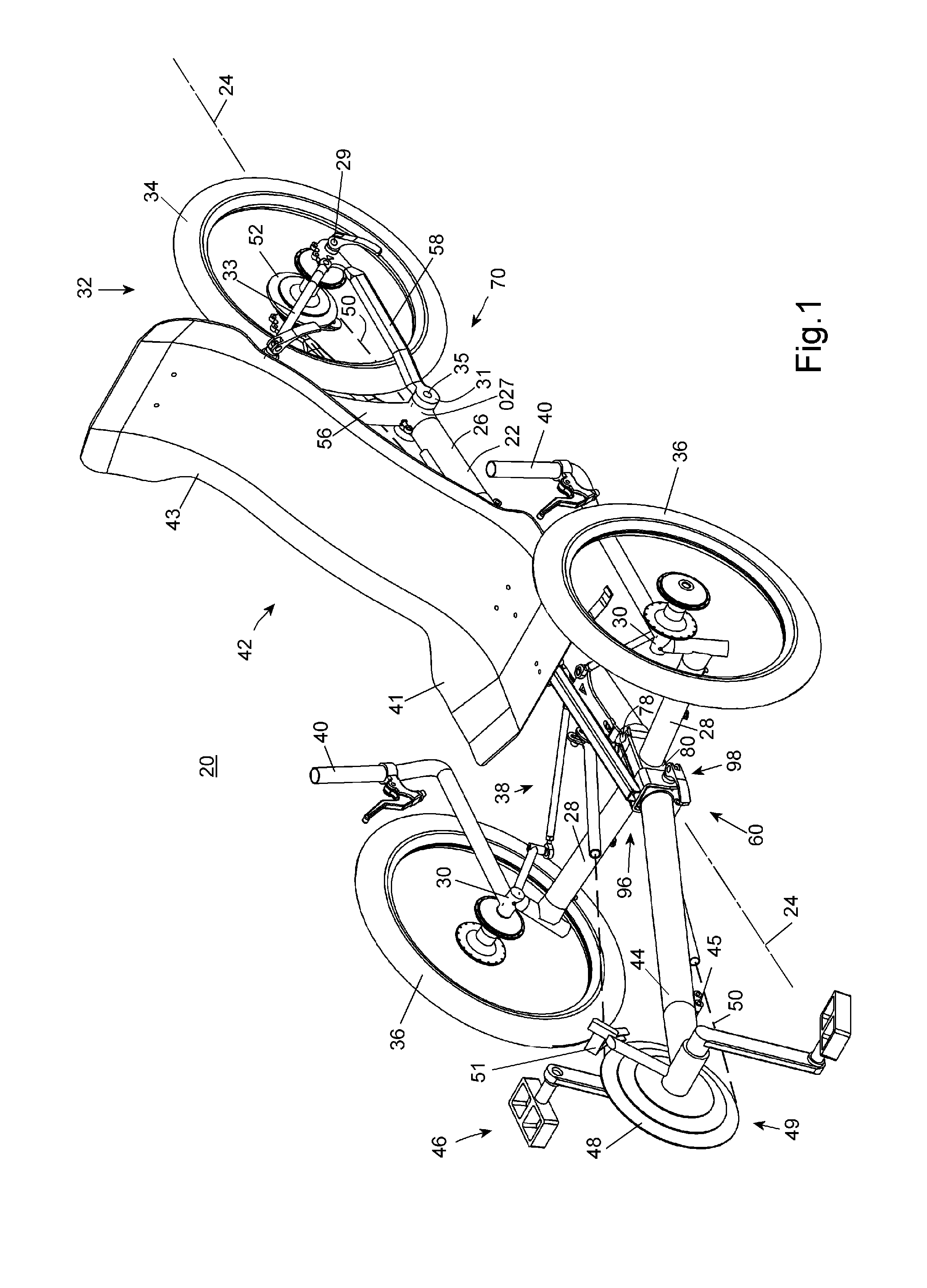
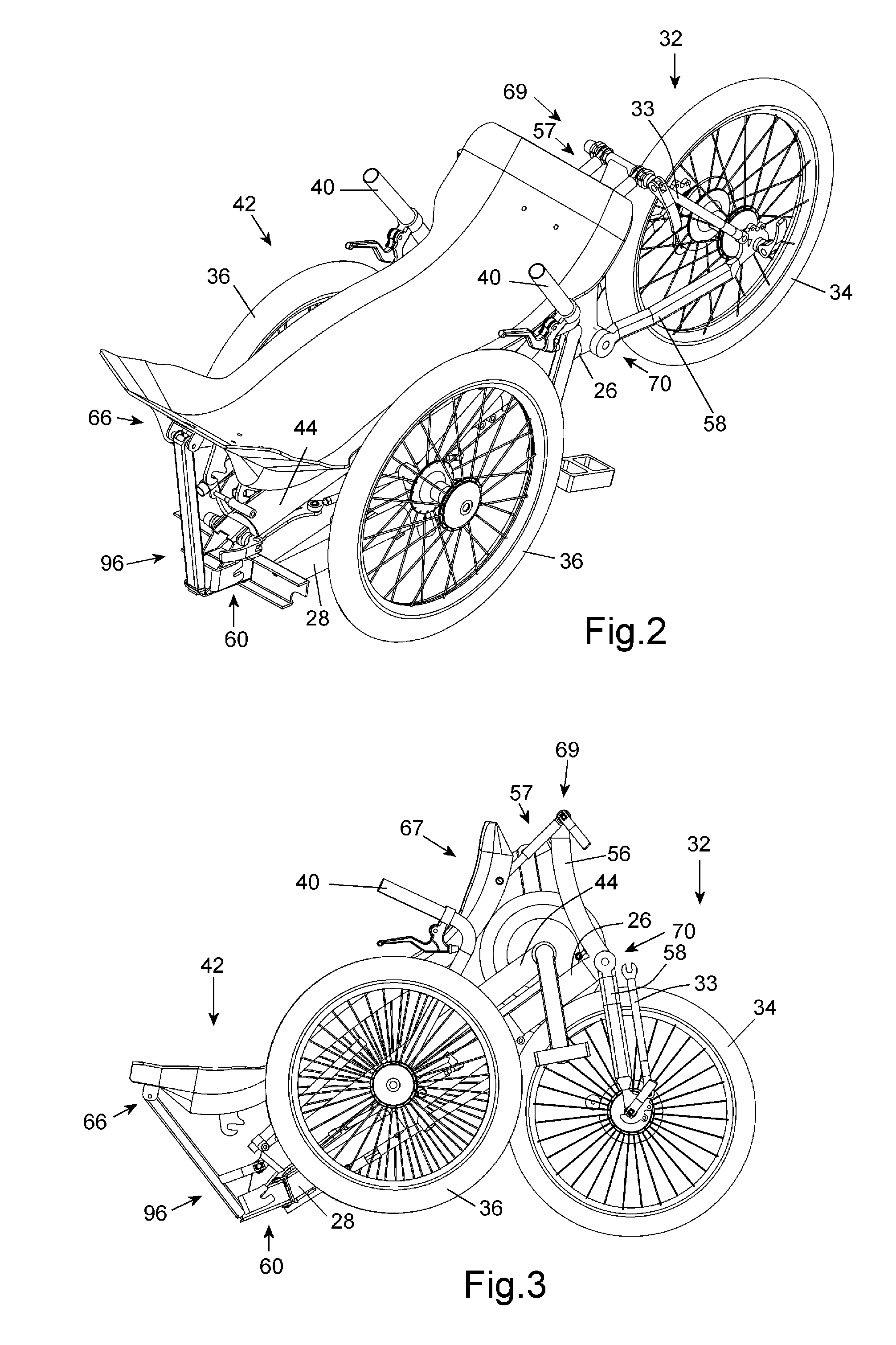
A tricycle having a spine frame, supported by a rear wheel and a pair of steerable front wheels; and a spine along a central axis. A pedal boom extends forwardly of the spine and supports a pedal crank assembly. A drive system connects the crank assembly with the rear wheel, and a seat is supported by the spine. The front wheels each support a lateral arm having a proximal end and a distal end with the front wheel pivotably attached at the distal end and an angular projection attached at the proximal end. A pivot connects each angular projection to the spine and allows the lateral arms to fold from a travel position, with distal ends spaced from the spine, to stowed positions alongside the spine. Clamping means on the spine arrests the angular projections in the travel position and releases the angular projections to allow folding of the lateral arms to their stowed position.
The tricycle provides a folding mechanism that is very compact in the travel position to allow the inclusion of performance frame geometry and an efficient drive system, and the tricycle can be collapsed quickly and easily to a compact size. The tricycle includes means to be collapsed quickly to several levels of compactness.

Problems solved by technology

The added wheel eliminates the need for the rider to balance to keep the vehicle upright, almost eliminating the possibility of falling from the vehicle, a major cause of injury with two-wheeled bicycles.
A vehicle known as the Challenge Concept Trike has tie-tods of aerofoil shape, which can lose their aerodynamic advantage if not aligned with tricycle travel.
Recumbent tricycles are necessarily long and wide to accommodate a reclining rider and they occupy a large amount of space for storage and for transporting in a motor vehicle, bus, train, an aeroplane or the like.
They are difficult to fit through gates and other narrow places.
This is a long recognized problem and there have been many attempts to design a tadpole tricycle that collapses easily and quickly to a compact form without compromising the performance properties of the tricycle when in use.
Also, this type can be collapsed to a small size but collapsing or re-assembling this type requires mechanical skill and usually tools, and takes a considerable time.
In all tricycles of this type the hinge opens at the bottom and so the weight of the rider applies a force to open the hinge if the hinge locking devices should ever release while being ridden, a significant problem.
Collapsing this type produces a still bulky assembly that requires some mechanical skill and considerable time to reassemble the removed parts.
In some embodiments the main collapsed assembly can be awkwardly rolled on the two front wheels but the width of the tricycle severely limits the usefulness of this function.
The collapsed tricycle still requires considerable storage space and the collapsed form has separated parts, including the seat, that need to be handled separately to transport.
This can lead to tricycle steering problems and instability especially when travelling at high speed.
This type also includes separate fasteners securing the seat, resulting in a plurality of fasteners on the tricycle and this type can take a considerable time to collapse and re-assemble.
The collapsed tricycle still requires considerable storage space and the collapsed form has separated parts, including the seat, that need to be handled separately to transport.
The lateral arms are oriented forward at a significant angle to the spine normal, resulting in longer lateral arms and deviating from the optimum frame geometry for high performance recumbent tricycles.
Any movement at the lateral arm pivots or fasteners, resulting from causes such as clearances or wear, is amplified at the distal ends of the lateral arms and can lead to tricycle steering problems and instability.
Additionally the separate pivot assemblies for each folding action provide no mutual re-enforcement or part sharing for weight reduction.
This type can be reduced to a compact size but collapsing this type takes a considerable time and the collapsed form has separated parts, including the seat, that need to be handled separately to transport.
While all the aforementioned recumbent tricycles are variously successful in collapsing a recumbent tricycle to a reduced size they are all deficient with respect to providing a tricycle capable of being quickly collapsed to a compact size and remain whole.
They thereby require a considerable time to collapse and the collapsing process produces separated parts.
Those that can collapse to a compact size by stowing the lateral arms and the boom alongside the spine also make significant compromises to the frame geometry of a performance tricycle.

Method used


Image

  • Collapsible Recumbent Tricycle
  • Collapsible Recumbent Tricycle
  • Collapsible Recumbent Tricycle

Examples


embodiment 60

Main arm assembly 72A differs from the first compound hinge embodiment 60 in that the assembly includes a sleeve plate 101A that further includes a generally vertically oriented channel 110A that supports at each distal end of each flange a sleeve 114A, and supports at its upper end sleeve 115A, and at the lower end a tongue 74A. Sleeve plate 101A can be variously fabricated by joining separate parts or by stamping and rolling from a flat plate or by casting or molding or forging methods as is common practice in fabricating hinges. Tubular member 100A is attached to the rear of sleeve plate 101A with holes 117A congruent with the outer surface of sleeves 114A. Tubular member 100A has a square hollow section shape at its front transitioning to a circular shape at the rear, the axis of the rear portion optionally being inclined at an angle to the compound hinge central axis 61A and form a socket or lug portion 118A for attaching to spine 26. Tubular member 100A also optionally include...

embodiment 395

Another embodiment of radius arm assembly, 395A is shown in FIG. 11A. This embodiment differs in that it includes a plate 412A that has a lower side shaped to sit on spine 26. Also extending upward from the upper side of the plate is axle 405A with a stepped end 407A. Radius arm 394A includes hole 402A by which it is pivotably connected to stepped end 407A of the axle forming radius arm pivot 404A. Pivot 404A can include bushes or bearings (not shown) and a fastener (not shown) holds radius arm 394A on stepped end 407A of the axle. Plate 412A also includes an elongate slot 414A. One or two fasteners (not shown) are fixed through that slot into holes (not shown) in the top surface of spine 26 to fasten plate 412A to the spine and to provide a slideable connection for the plate. The fasteners are tightened to fix the slideable connection in the required position. Similar to embodiment 395, tie rods 392 can be adjusted to length for the desired toe-in and pivot 404A can be positioned u...

first embodiment

Yet another embodiment of the radius arm assembly, 395B can include radius arm 394B, which is shown in FIG. 11B. The radius arm assembly can be attached using hole 402B to the axle 405 (FIG. 11) of the The radius arm differs in that a slot 397B divides the arm from the arc end into two narrower arms 394L and 394R each having at the arc end a hole 400B. Arms 394L and 394R have threaded holes (not shown) through the side accepting fasteners 398B. When the fasteners are tightened the ends of the fasteners can press together pushing apart the arc ends of arms 394L and 394R thereby expanding the width of slot 397B and increasing the spacing between holes 400B.

Also, a fastener 399B is fitted through another hole (not shown) through the side of arm 394L and into a threaded hole (not shown) through the side of arm 394R. When the fastener is tightened it pulls together arms 394L and 394R reducing the width of slot 397B and decreasing the spacing between holes 400B. As can be appreciated fas...


PUM


Abstract

One embodiment of a tricycle (20) having a spine frame (22), supported by a rear wheel (34) and a pair of steerable front wheels (36), and supporting a recumbent seat (42) pivotably attached at its rear. A pedal boom (44) extends forwardly of the spine (26) and supports a pedal crank assembly (46). The front wheels each support a lateral arm (28) with the front wheel pivotably attached at the distal end and an angular projection (80) attached at the proximal end. A pivot (78) connects each angular projection to the spine, allowing the lateral arms and attached front wheels to fold to a stowed position alongside the spine. Another pivot (84) connects the boom to the spine, allowing the boom fold back to a stowed position against the spine. In the travel position, clamping means arrest the angular projections, and can arrest the boom and seat. The tricycle is collapsible to several levels of compactness. Other embodiments are described and shown.

Description

FEDERALLY SPONSORED RESEARCHNot Applicable.SEQUENCE LISTING OR PROGRAMNot ApplicableBACKGROUND OF THE INVENTION1. Field of the InventionThis invention is generally related to small land vehicles and, more particularly to recumbent tricycles.2. Description of Related ArtRecumbent tricycles or trikes are closely related to recumbent bicycles, but have three wheels instead of two. The added wheel eliminates the need for the rider to balance to keep the vehicle upright, almost eliminating the possibility of falling from the vehicle, a major cause of injury with two-wheeled bicycles. A recumbent tricycle is a tricycle that places the rider in a laid-back reclining position and which has a pedal crank in the front area of the tricycle. The reclined, legs-forward position of the rider's body presents a smaller frontal area and delivers an aerodynamic advantage over conventional tricycles. Additionally the rider's weight is distributed over the rider's back and buttocks on a seat that can b...

Claims


Application Information

Patent Timeline
Patent Type & Authority Applications(United States)
IPC IPC(8): B62K15/00B62K5/02B62M1/02B62M1/36
CPCB62K3/005B62K5/05B62M1/36B62K15/00B62K15/008B62K5/08
Inventor BALL, ALAN ROYBALL, ERIC JOHN
Owner BALL ALAN ROY
Why Eureka
Try Eureka