Image pickup apparatus that shoots subject viewed through viewfinder, control method therefor, and storage medium

a pickup apparatus and image technology, applied in the field of image pickup apparatus, can solve the problems of erroneous operation, conventional image pickup apparatus described above, and no contribution to preventing camera malfunction

Inactive Publication Date: 2011-10-13
CANON KK
View PDF11 Cites 38 Cited by
  • Summary
  • Abstract
  • Description
  • Claims
  • Application Information

AI Technical Summary

Benefits of technology

[0011]The present invention provides an image pickup apparatus that reduces the likelihood that when a user operates a display screen with a fingertip while not looking through a viewfinder, the user's fingertip will be falsely detected, and makes it less likely that erroneous operation resulting from the false detection will occur, a control method for the image pickup apparatus, and a computer-readable storage medium storing a program for causing a computer to implement the method.

Problems solved by technology

Thus, in cameras of which eye proximity sensor and touch panel are operated in combination, there may be a case where erroneous operation occurs due to the tip of a user's nose touching the touch panel when the user looks through the viewfinder.
However, the conventional image pickup apparatuses described above present problems explained hereafter.
The techniques described in Japanese Laid-Open Patent Publication (Kokai) No. 2001-059984 and Japanese Laid-Open Patent Publication (Kokai) No. 2004-165934 relate to the prevention of erroneous operation in the touch panel when the user looks through the viewfinder, but do not contribute at all to preventing malfunction of the camera resulting from false detection by the eye proximity sensor.
This makes it impossible to perform desired operations.
Namely, when the user is trying to touch the area where the aperture value “F8.0” is displayed, an erroneous operation occurs in which display is turned off, making it impossible to change shooting conditions.

Method used


Image

  • Image pickup apparatus that shoots subject viewed through viewfinder, control method therefor, and storage medium
  • Image pickup apparatus that shoots subject viewed through viewfinder, control method therefor, and storage medium
  • Image pickup apparatus that shoots subject viewed through viewfinder, control method therefor, and storage medium

Examples


first embodiment

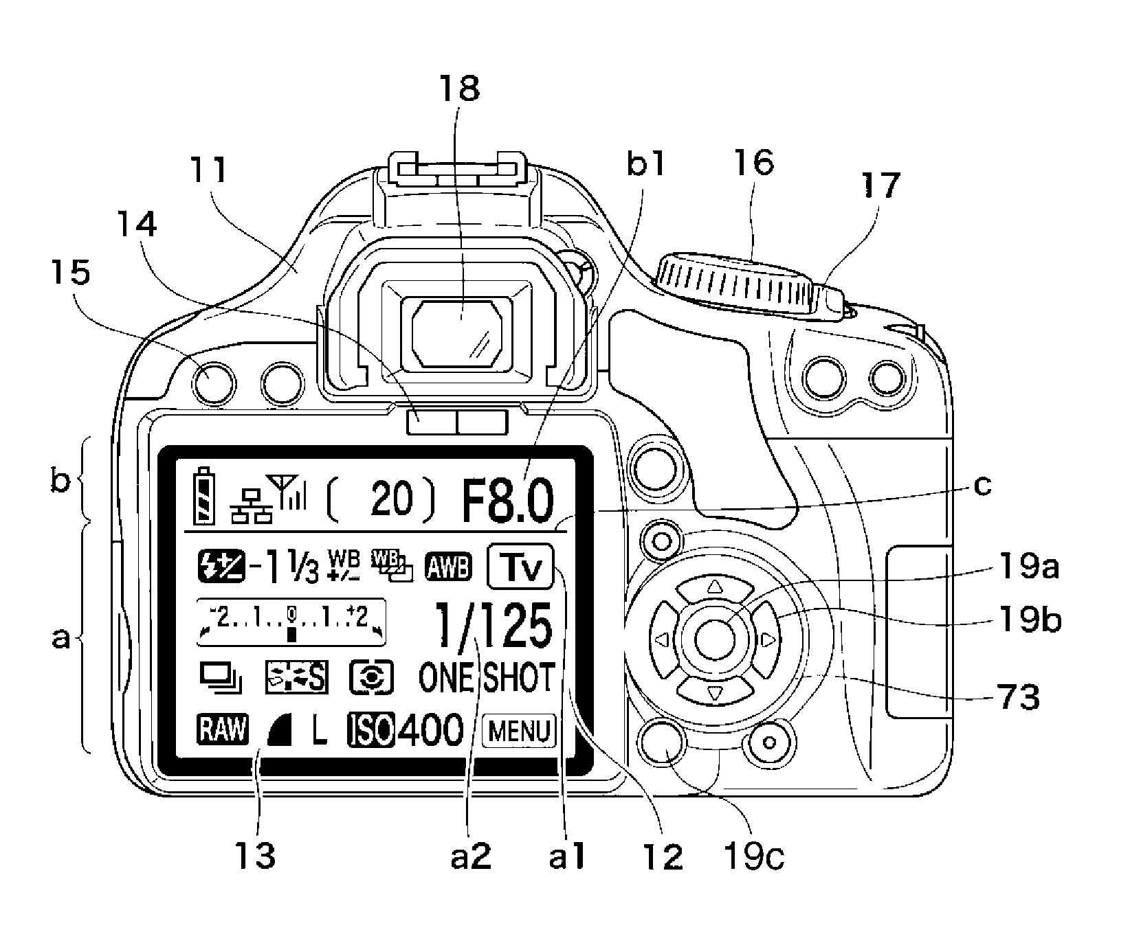
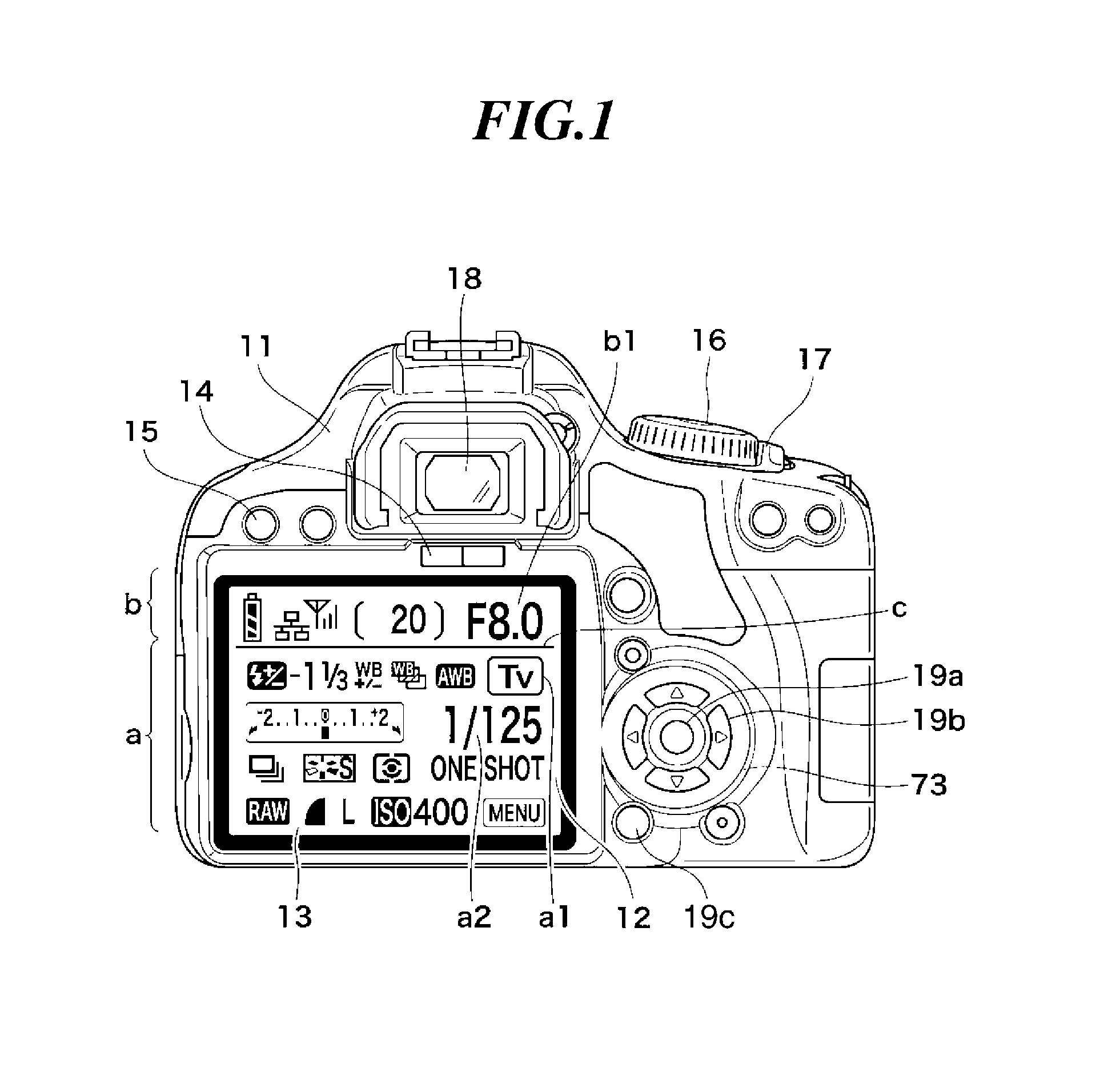
[0028]FIG. 1 is a view showing an appearance of a back side of a digital single-lens reflex camera (hereafter abbreviated as the camera) 11 which is the present invention. On a back side of the camera 11, there is provided a TFT liquid crystal display unit (hereafter referred to merely as the TFT) 12 which is an information display unit that displays taken images and settings, operating state, and so on of the camera 11.

[0029]A transparent transmissive touch panel (hereafter abbreviated as the touch panel) 13 is mounted on a surface of the TFT 12. The touch panel 13 detects not only whether or not a user's fingertip has touched the TFT 12, but also which area of the TFT 12 has been touched by the fingertip (touch position). Thus, which display area of the TFT 12 has been touched by the user can be determined by comparing contents displayed on the TFT 12 and a touch position with each other.

[0030]The camera 11 is also equipped with a number of operation switches such as a power switc...

second embodiment

[0088]In the camera 11 the second-type display objects are displayed in a negative-positive reversed manner against the first-type display objects. This makes the difference between the first-type display objects and the second-type display objects visibly clear.

[0089]When operating the touch panel of the TFT 12, the user can visually recognizes at a glance that a second-type display object which he / she is going to touch does not lie close to the eye proximity sensor 14. As a result, the likelihood of the user putting a fingertip close to the eye proximity sensor 14 can be further reduced, and the same effects as in the first embodiment can be more reliably obtained.

[0090]FIG. 6 is a view showing an appearance of a back side of the camera 11 which is a third embodiment of the present invention. The arrangement and operation of the camera 11 are substantially the same as in the first embodiment described above. The components same as those of the first embodiment are designated by t...

fourth embodiment

[0092]Next, a description will be given of a camera as an image pickup apparatus according to the present invention.

[0093]A camera 40 according to the fourth embodiment is arranged such that the TFT 12 is disposed on a vari-angle display unit (a second housing) rotatably mounted on a main body (a first housing) of the camera 11 shown in FIG. 1 such as to be able to open and close, and touch operations on display objects can be accepted regardless of whether they are in the display range a or b only when the vari-angle display unit occupies a certain position.

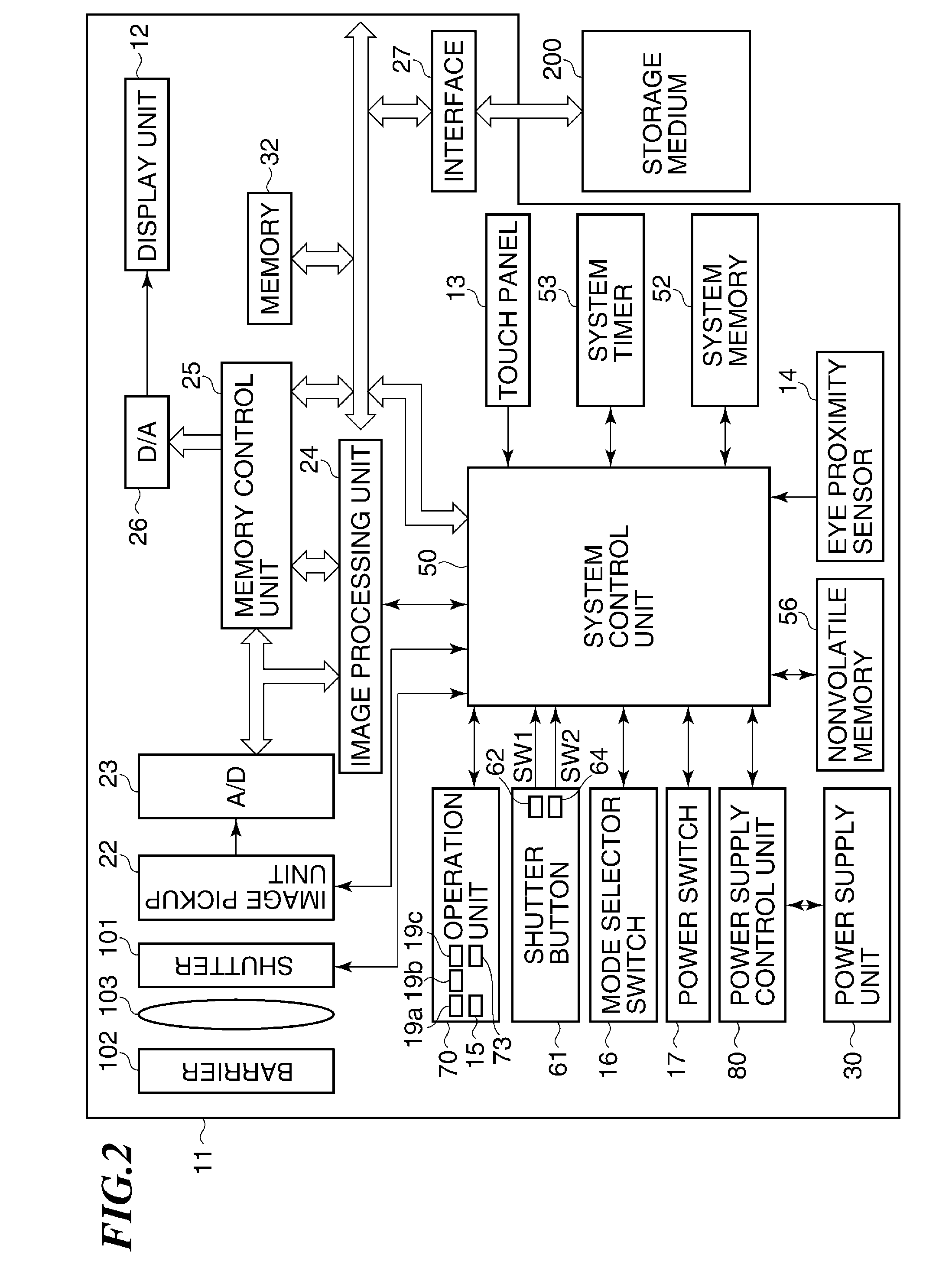
[0094]A hardware arrangement (not shown) of the camera 40 according to the fourth embodiment adds, to the hardware arrangement shown in the block diagram of FIG. 2, a position detection unit that is capable of communicating with the system control unit 50 and detects a position of the vari-angle display unit, and a dial 803 included in the operation unit 70.

[0095]FIGS. 8A to 8D are diagrams useful in explaining positions to whic...


PUM


Abstract

An image pickup apparatus that reduces the likelihood that when a user operates a display screen with a fingertip while not looking through a viewfinder, the user's fingertip will be falsely detected, and makes it less likely that erroneous operation resulting from the false detection will occur. When an eye proximity sensor detects an object approaching, the light emission luminance of a display unit is reduced, or display on the display unit is turned off. When the eye proximity sensor has not detected an object approaching, first-type display objects that execute assigned functions in response to touch operations are displayed farther away from the eye proximity sensor on a display surface of the display unit than second-type display objects that do not execute assigned functions even when touched. When a touch on any of the first-type display objects is detected, a function assigned to the first-type display object is executed.

Description

BACKGROUND OF THE INVENTION[0001]1. Field of the Invention[0002]The present invention relates to an image pickup apparatus that shoots a subject viewed through a viewfinder, a control method therefor, and a computer-readable storage medium storing a program for causing a computer to implement the method.[0003]2. Description of the Related Art[0004]In recent years, a number of cameras which have an information display unit, typified by a TFT liquid crystal display, mounted on a back side of the camera so as to display states of the camera. Among such cameras, there are those equipped with an eye proximity sensor for automatically turning off display on the information display unit because a display surface of the information display unit is dazzling when a user looks through a viewfinder. This eye proximity sensor merely detects whether or not an object has approached, and in general, an infrared sensor is used as the eye proximity sensor.[0005]On the other hand, cameras in which a t...

Claims


Application Information

Patent Timeline
Patent Type & Authority Applications(United States)
IPC IPC(8): H04N5/225G03B7/30G03B17/00G03B17/02G03B17/18
CPCG03B13/02G03B2213/025H04N5/23293H04N5/23216G06F3/0416H04N23/62H04N23/631H04N23/633H04N23/00
Inventor CHUREI, KIYOKAZU
Owner CANON KK
Why Eureka
Try Eureka