Stereoscopic image pair alignment apparatus, systems and methods

a technology of stereoscopic image and alignment apparatus, applied in the field of stereoscopic image pair alignment, can solve the problems of horizontal and vertical misalignment, excessive or insufficient horizontal disparity, etc., and achieve the effect of reducing or eliminating undesirable horizontal and vertical disparity components

Inactive Publication Date: 2011-10-13
TEXAS INSTR INC
View PDF6 Cites 30 Cited by
  • Summary
  • Abstract
  • Description
  • Claims
  • Application Information

AI Technical Summary

Benefits of technology

[0064]Apparatus, systems, and methods described herein operate to generate an image alignment shift vector used to shift left and right image portions of a stereoscopic image with respect to each other in order to reduce or eliminate undesirable horizontal and vertical disparity components. Processing power is conserved by correlating vertical and horizontal projections of pixel luminance values to derive vertical and horizontal components of the image alignment shift vector in contrast to performing image identification on an entire pixel matrix.

Problems solved by technology

However, inaccuracies associated with stereoscopic imaging result in horizontal and vertical misalignment referred to as horizontal and vertical disparity, respectively.
Although proper amounts of horizontal disparity are responsible for the three-dimensional effect, stereoscopic imaging from cameras typically results in excessive or insufficient horizontal disparity.
Unnatural horizontal disparity results from the cameras' fixed lenses, which are unable to rotate about the horizontal plane in accordance with the distance to the focal plane as do human eyes.
Vertical disparity may result from vertical misalignment between right and left imaging devices.
Vertical disparity and unnatural amounts of horizontal disparity create visual crosstalk and may introduce visual artifacts and viewing discomfort.
However, doing so first requires estimating the amounts of disparity to correct for.
These methods may be computationally intensive and difficult to implement in real time for video.

Method used


Image

  • Stereoscopic image pair alignment apparatus, systems and methods
  • Stereoscopic image pair alignment apparatus, systems and methods
  • Stereoscopic image pair alignment apparatus, systems and methods

Examples


Embodiment Construction

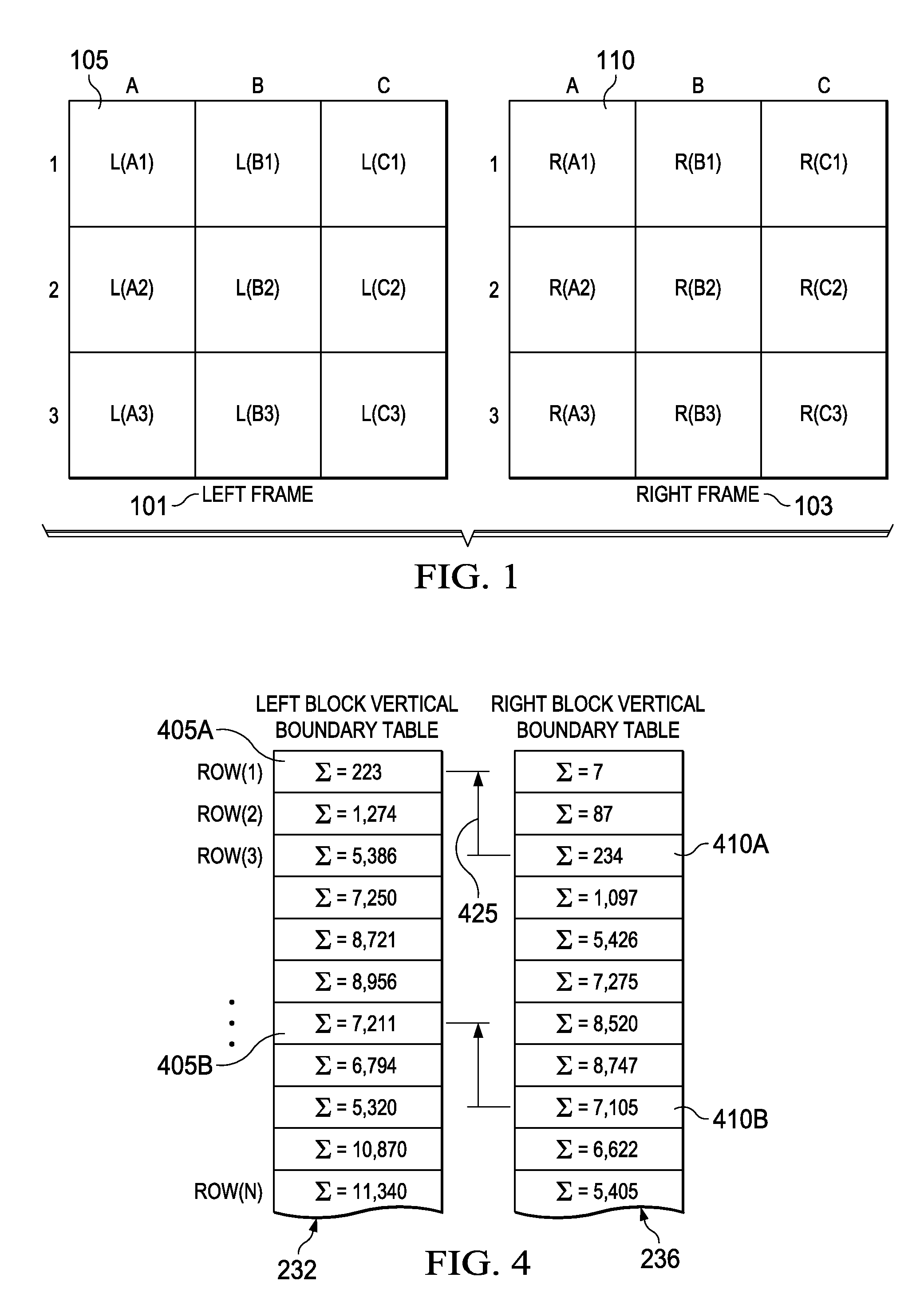
[0019]FIG. 1 is a diagram of a stereoscopic image pair divided into blocks of pixels according to various example embodiments of the invention. Each of the left frame 101 and the right frame 103 is divided into a number, shape, and size of pixel blocks that may differ from one embodiment to another. In some embodiments, a pixel block maybe identified for the right frame of the same shape, size, and position of each pixel block identified in the left frame. For example, left frame pixel block 105 is of the same shape, size, and position as right frame pixel block 110.

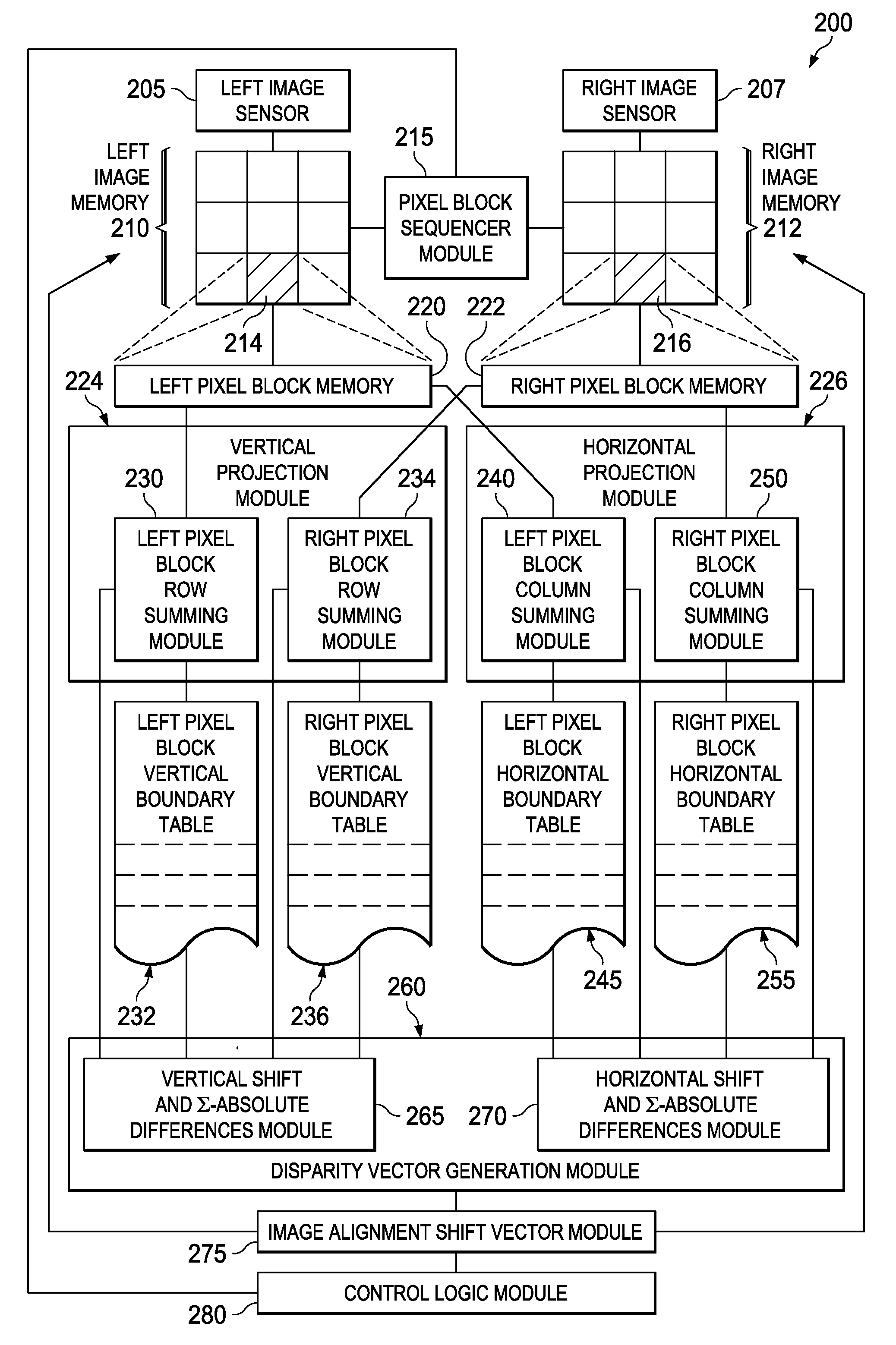
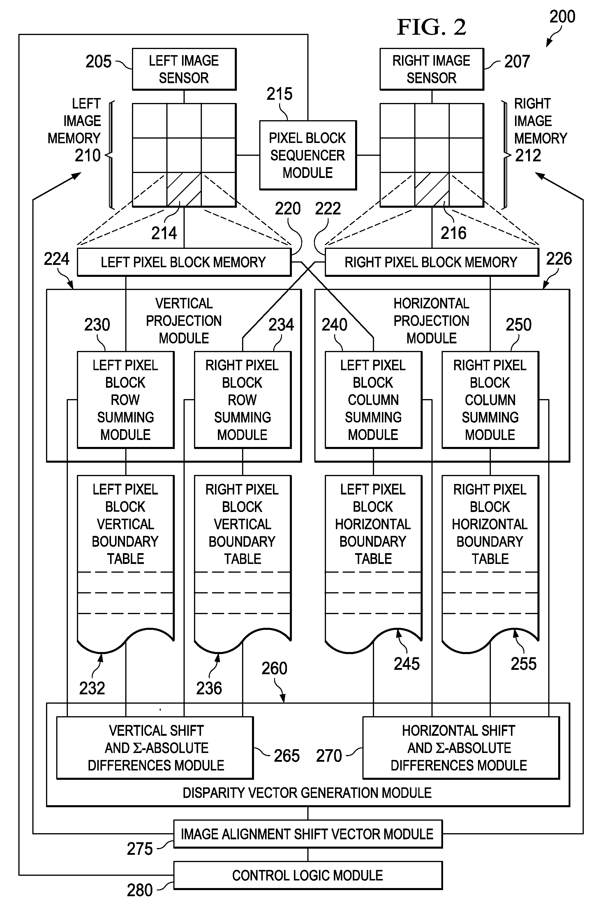
[0020]FIG. 2 is a block diagram of a stereoscopic image alignment system 200 according to various example embodiments. In some embodiments, the system 200 may include left and right image sensors 205 and 207, respectively. Other embodiments of the stereoscopic image alignment system 200 may operate on pre-existing stereoscopic images. The image sensors 205 and 207 create left and right images by capturing photons at pixe...


PUM


Abstract

Apparatus, systems, and methods disclosed herein operate to produce an image alignment shift vector used to shift left and right image portions of a stereoscopic image with respect to each other in order to reduce or eliminate undesirable horizontal and vertical disparity components. Vertical and horizontal projections of luminance value aggregations from selected left and right image pixel blocks are correlated to derive vertical and horizontal components of a disparity vector corresponding to each left/right pixel block pair. Disparity vectors corresponding to multiple image blocks are algebraically combined to yield the image alignment shift vector. The left and/or right images are then shifted in proportion to the magnitude of the image alignment shift vector at an angle corresponding to that of the image alignment shift vector.

Description

PRIORITY CLAIM[0001]This application claims the benefit of priority under 35 U.S.C. §119(e) to U.S. Provisional Patent Application Ser. No. 61 / 322,194 titled “Auto-alignment of Stereoscopic Image-pairs Using Boundary Signals,” filed on Apr. 8, 2010 and incorporated herein by reference in its entirety.TECHNICAL FIELD[0002]Embodiments described herein relate to apparatus and methods associated with imaging technology, including structures and methods associated with stereoscopic image pair alignment.BACKGROUND INFORMATION[0003]As a three-dimensional pictures and movies become increasingly popular, methods of stereoscopic imaging are being refined to create images of increasing fidelity. One area of interest in this regard is that of left and right image alignment.[0004]Three-dimensional effects are created by slight differences between left and right images resulting from slightly different angular views from the left and right eyes. Left and right cameras used in stereoscopic imaging...

Claims


Application Information

Patent Timeline
Patent Type & Authority Applications(United States)
IPC IPC(8): G06K9/00
CPCG06T7/0026G06T2207/20228G06T2207/20021G06T2207/10012G06T7/32
Inventor KOTHANDARAMAN, SREENIVASHONG, WEIBATUR, AZIZ
Owner TEXAS INSTR INC
Why Eureka
Try Eureka