Railcar primary suspension

a primary suspension and railcar technology, applied in the direction of axle box mounting, rail components, rubber-like material springs, etc., can solve the problems of low workability and require work proficiency, and achieve the effect of reducing the need for maintenance work, improving assembly workability, and suppressing the rotational vibration of the sha

Active Publication Date: 2011-10-20
KAWASAKI RAILCAR MFG CO LTD
View PDF11 Cites 27 Cited by
  • Summary
  • Abstract
  • Description
  • Claims
  • Application Information

AI Technical Summary

Benefits of technology

[0009]According to the above configuration, a portion of each fitting groove and a portion of the corresponding projecting portion, the portions contacting each other, respectively have the arc surfaces. Therefore, even if the fastening torque of the fastening members increases and thereby the contact pressure of the projecting portion against the fitting groove increases, the contact pressure is exerted in multiple directions in a radially distributed manner. This prevents a stress concentrated in a single direction from being exerted on the receiving seat. This allows the fastening members, which are used for fixing the cover members to the respective receiving seats, to be fastened with a standard torque, similar to other fastening members. This significantly improves assembling workability. Moreover, a portion of each projecting portion and a portion of the corresponding cover member, the portions contacting each other, respectively have the flat surfaces. Accordingly, rotational vibration of the shaft is sufficiently suppressed. This prevents wear between the projecting portion and the fitting groove, thereby reducing the necessity of maintenance work.

Problems solved by technology

This causes low workability and requires proficiency for the work.

Method used


Image

  • Railcar primary suspension
  • Railcar primary suspension
  • Railcar primary suspension

Examples


embodiment 1

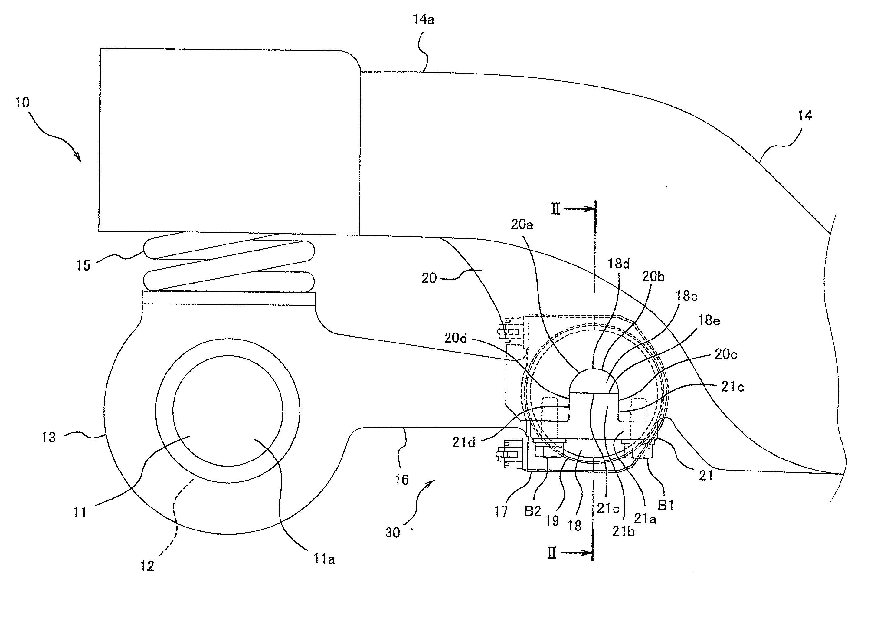
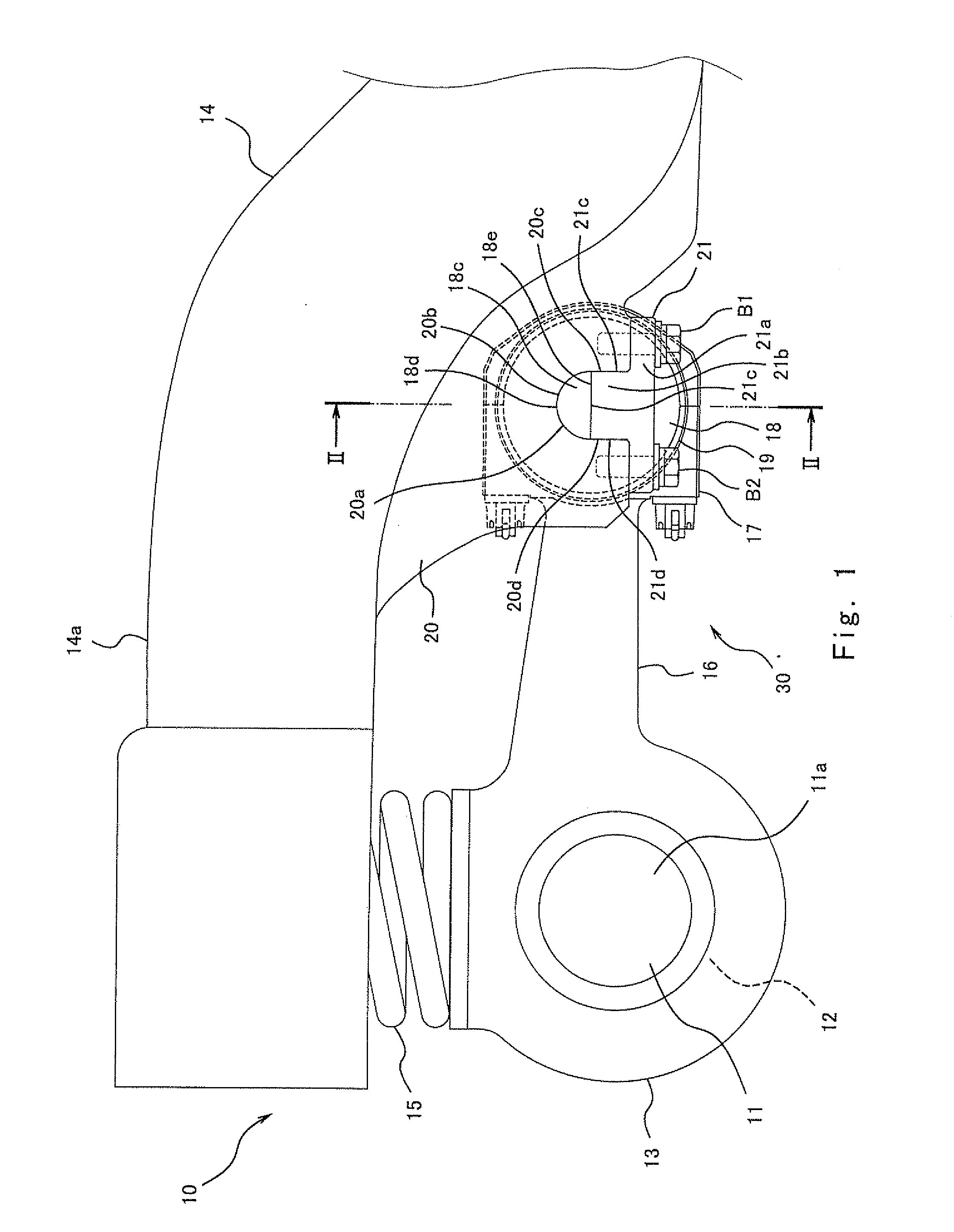
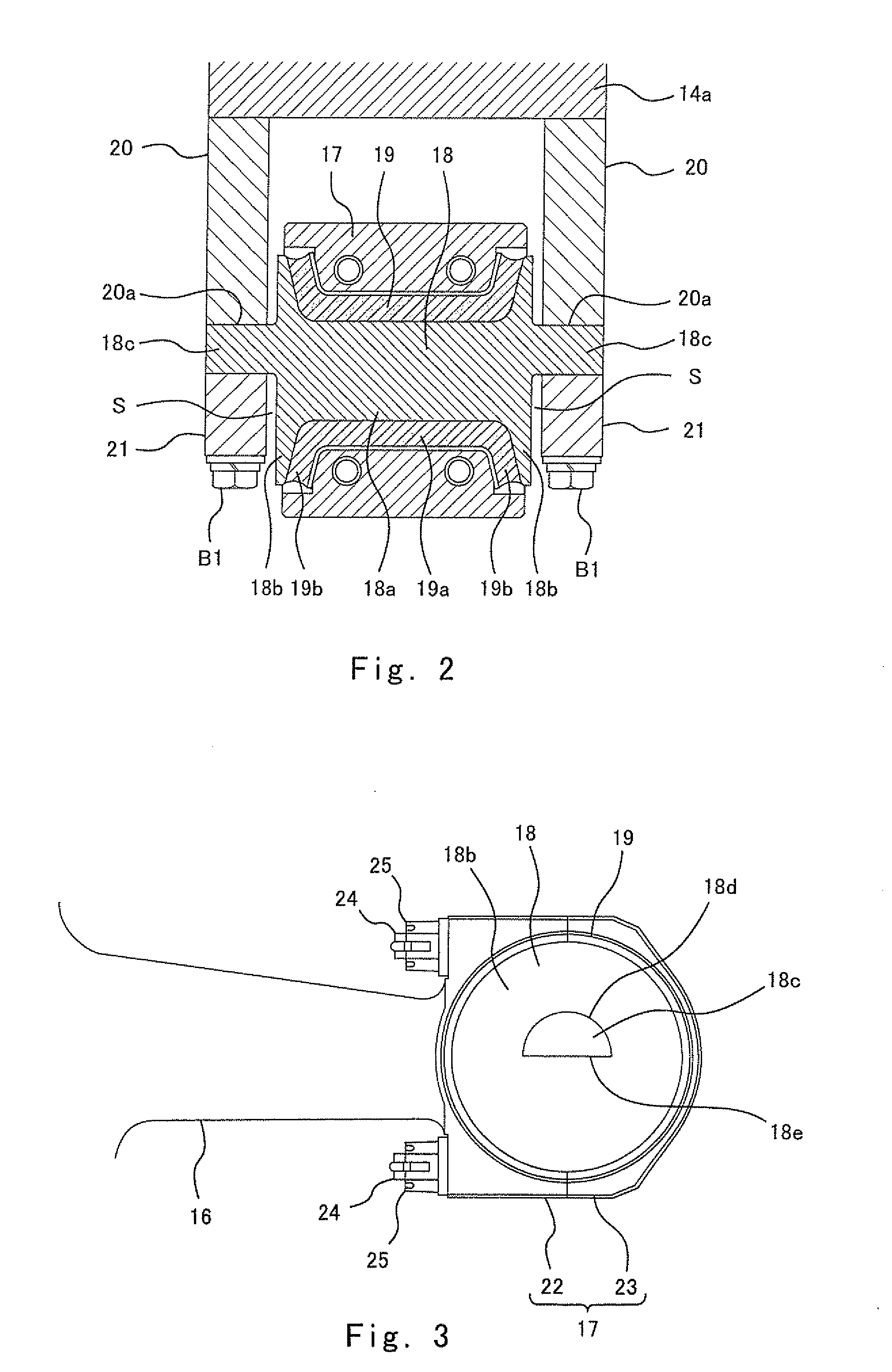
[0022]FIG. 1 is a side view of a primary suspension 10 according to Embodiment 1 of the present invention. FIG. 2 is a cross-sectional view taken along line II-II of FIG. 1. FIG. 3 is a main part enlarged view without a receiving seat 20 and a cover member 21 which are shown in FIG. 1. FIG. 4 is a perspective view of a shaft 18 shown in FIG. 3. FIG. 5 is a main part enlarged view showing a state where bolts B1 and B2 shown in FIG. 1 are being fastened. As shown in FIG. 1, a railcar primary suspension 10 of the present embodiment is of the radius arm (axle beam) type. The primary suspension 10 includes an axle box 13 configured to accommodate a bearing 12 for rotatably supporting an axle 11a of a wheelset 11 including the axle 11a and wheels (not shown) provided at both ends of the axle 11a. An axle spring 15, which is a coil spring, is interposed between the axle box 13 and a side frame 14a (a side beam) of a truck frame 14 disposed above the axle box 13.

[0023]The axle box 13 is con...

embodiment 2

[0033]FIG. 6, corresponding to FIG. 5 of Embodiment 1, shows an primary suspension 110 according to Embodiment 2 of the present invention. As shown in FIG. 6, the primary suspension 110 of the present embodiment is different from Embodiment 1 in that projecting portions 118c of a shaft 118 and cover members 121 have different shapes from those of the projecting portions 18c of the shaft 18 and the cover members 21. It should be noted that in FIG. 6, the same components as those of Embodiment 1 are denoted by the same reference signs as those used in Embodiment 1. The external shapes of the projecting portions 118c of the shaft 118 substantially match the external shapes of the fitting grooves 20a. Specifically, each projecting portion 118c includes: an arc surface 118d which is a semi-circular upper surface; side surfaces 118f and 118g extending in the upper-lower direction, which are continuous with lower edges at both sides of the arc surface 118d, respectively; and a lower surfac...

embodiment 3

[0035]FIG. 7, corresponding to FIG. 2 of Embodiment 1, shows an primary suspension 210 according to Embodiment 3 of the present invention. As shown in FIG. 7, the primary suspension 210 of the present embodiment is different from Embodiment 1 in that both side surfaces of a shaft 218 are in contact with the inner surfaces of the respective receiving seats 20. It should be noted that in FIG. 7, the same components as those of Embodiment 1 are denoted by the same reference signs as those used in Embodiment 1. To be specific, the shaft 218 includes: a cylindrical portion 218a; a pair of conical flange portions 218b respectively provided at both sides of the cylindrical portion 218a in the vehicle width direction; and projecting portions 218c outwardly protruding in the vehicle width direction from side surfaces of the pair of respective flange portions 218b. The side surfaces, in the vehicle width direction, of the respective flange portions 218b are in contact with the inner surfaces ...


PUM


Abstract

A railcar primary suspension is configured to couple an axle box to a truck frame by a coupling mechanism. The coupling mechanism includes: a radius arm including a tubular part which has openings at both sides thereof; a shaft inserted into the tubular part and provided with projecting portions formed at both side surfaces of the shaft; a pair of receiving seats including fitting grooves in which the respective projecting portions are fitted; cover members configured to support the respective projecting portions; and fastening members configured to fix the cover members to the respective receiving seats. A portion of each fitting groove and a portion of the corresponding projecting portion, the portions contacting each other, respectively have arc surfaces, and a portion of each projecting portion and a portion of the corresponding cover member, the portions contacting each other, respectively have flat surfaces.

Description

BACKGROUND OF THE INVENTION[0001]1. Field of the Invention[0002]The present invention relates to a railcar primary suspension configured to couple an axle box, which accommodates a bearing for supporting an axle, to a side frame of a truck frame by a connecting mechanism.[0003]2. Description of the Related Art[0004]In a railcar truck, an axle box accommodating a bearing for supporting an axle is supported by an primary suspension in a manner that allows the axle box to be displaced with respect to the truck frame. There are various types of primary suspensions. For example, in the case of an primary suspension of an radius arm type, an axle spring which is a coil spring is interposed between an axle box and a side frame of a truck frame disposed above the axle box, and a tip end portion of a radius arm extending in a vehicle longitudinal direction from the axle box is supported in a displaceable manner by receiving seats extending downward from the truck frame (e.g., see Japanese Pa...

Claims


Application Information

Patent Timeline
Patent Type & Authority Applications(United States)
IPC IPC(8): B61F5/28
CPCF16F1/38B61F5/325
Inventor NISHIMURA, TAKEHIROOKUMURA, YASUFUMI
Owner KAWASAKI RAILCAR MFG CO LTD
Why Eureka
Try Eureka