Corrugated plate structure having solar panel

a technology of corrugated plates and solar panels, which is applied in the direction of heat collector mounting/support, pv power plants, light and heating equipment, etc., can solve the problems of occupying a large space, affecting and the weight of the support bracket is excessively high, so as to reduce the bearing load of the building, simplify the construction operation of the solar panel, and improve the appearance of the building

Inactive Publication Date: 2011-10-20
A2PEAK POWER
View PDF0 Cites 2 Cited by
  • Summary
  • Abstract
  • Description
  • Claims
  • Application Information

AI Technical Summary

Benefits of technology

[0012]According to the corrugated plate structure having the solar panel of the present invention, the solar panel can be directly mounted on the corrugated plate to serve as the main appearance of a roof of a building, while maintaining the original appearance design of the building, without impairing the appearance of the building. Furthermore, the problem that a support bracket structure is required for installing the solar panel in the prior art is solved, so that the construction operation of the solar panel is simplified, and the bearing load of the building can also be reduced.

Problems solved by technology

However, currently available support brackets are mostly made of an aluminum extrusion material or an angle steel material, so the cost and the selling price are excessively high.
Furthermore, during transportation, the support brackets have an excessively heavy weight and an excessively huge volume, and occupy a large space.
The support brackets are not easy to carry, especially for construction operation of installation on the top floor.
Besides the difficulty in construction and transportation, the bearing load of the roof of the building is also increased, and the overall appearance of the building is seriously affected when the solar panel is mounted on the roof through the support bracket.
Furthermore, the commercially available support brackets have a complex overall structure and an excessively large number of component combinations, some combined structures can only be assembled by electric welding, and the structure can not be changed after assembly, so that the solar panel cannot be dismounted for replacement.

Method used


Image

  • Corrugated plate structure having solar panel
  • Corrugated plate structure having solar panel
  • Corrugated plate structure having solar panel

Examples


second embodiment

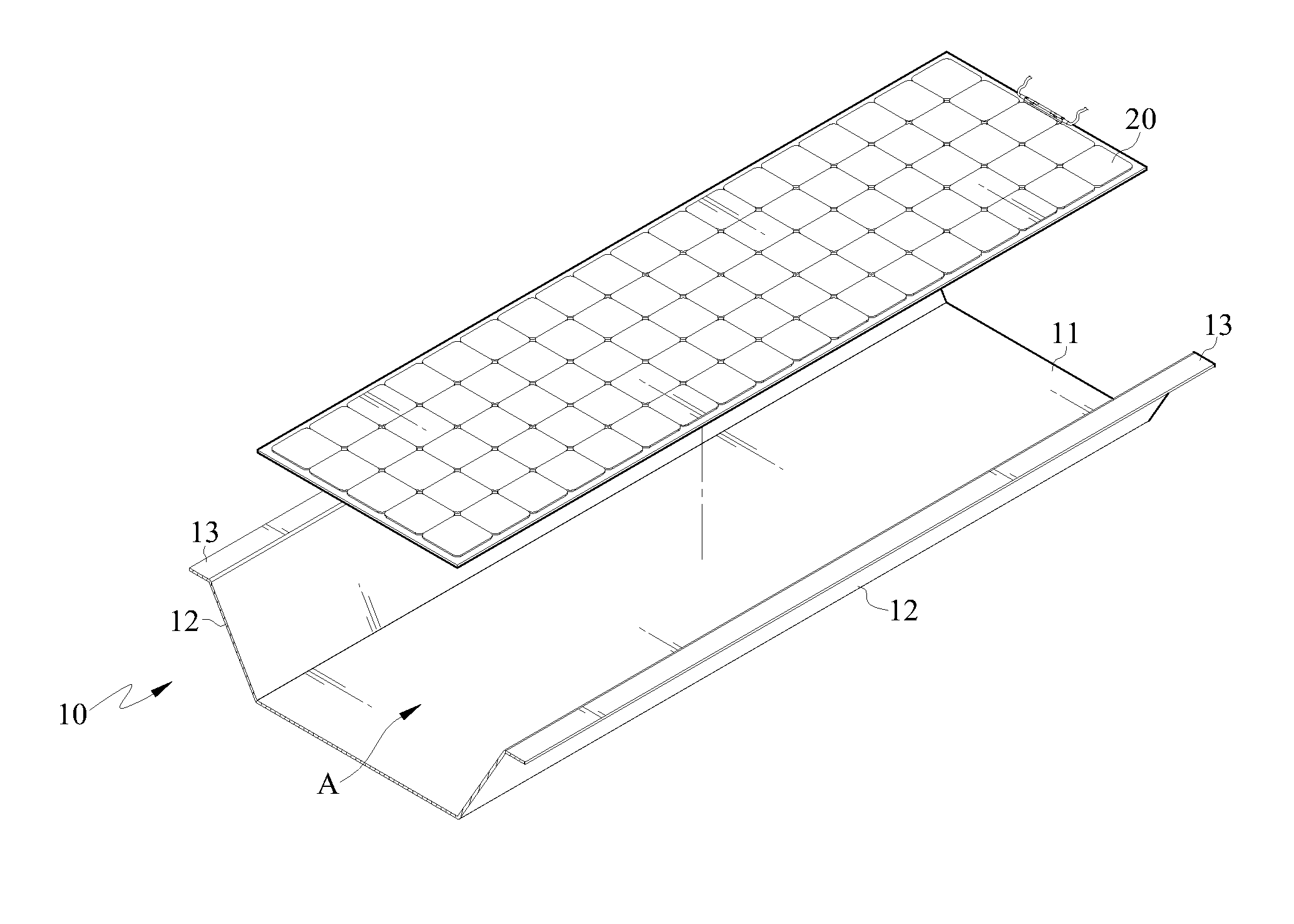
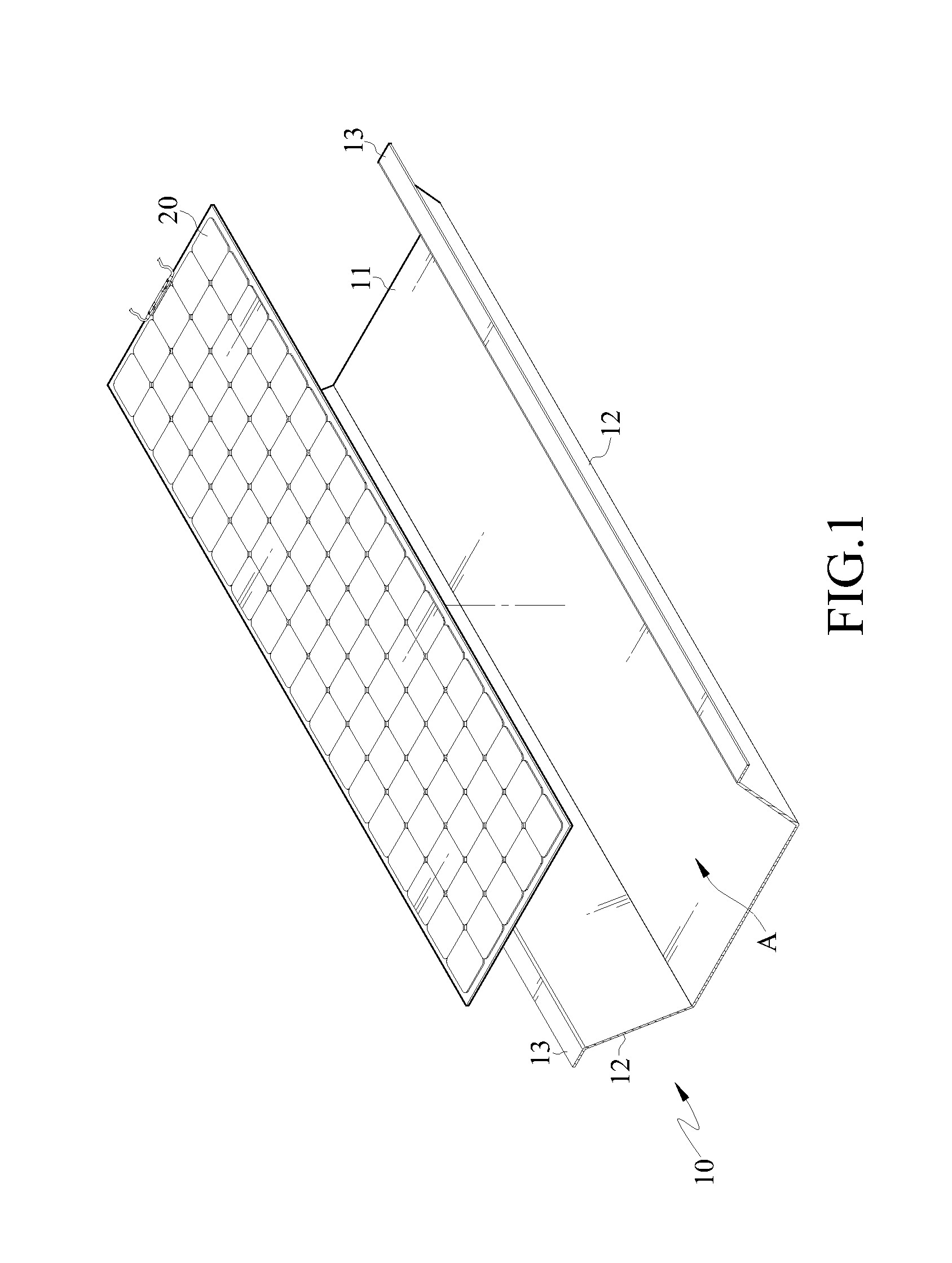
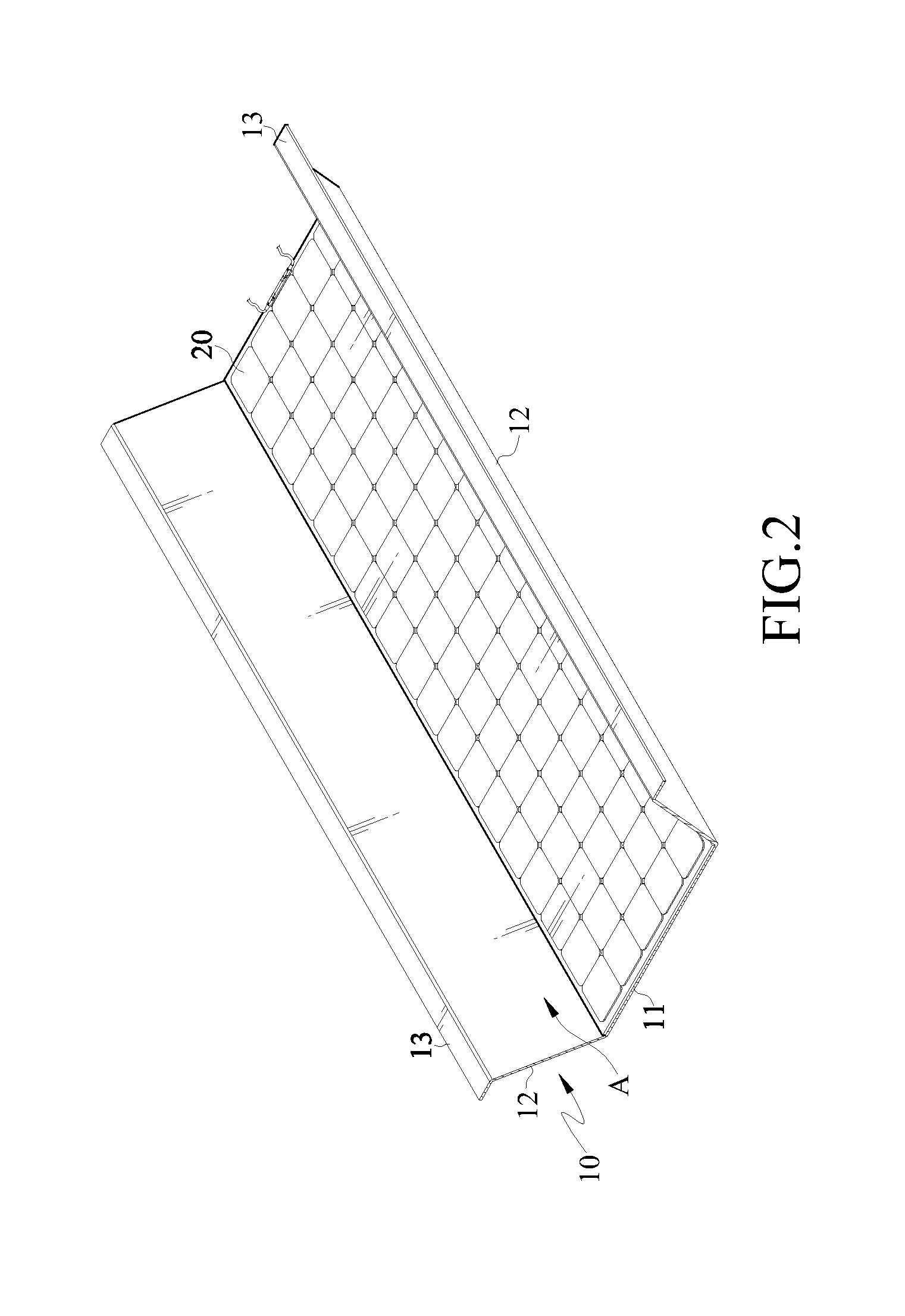
[0032]In this embodiment, the corrugated plate 10 is not limited to only be formed with one bottom plate portion 11, and a plurality of bottom plate portions 11 may also be formed on the corrugated plate 10 at the same time. FIGS. 4 and 5 are a schematic exploded view and a schematic assembly view of a corrugated plate structure having a solar panel according to the present invention. As shown in FIGS. 4 and 5, ends of the side plate portions 12 at two opposite sides of each bottom plate portion 11 are respectively connected with a top plate portion 13. In this way, a plurality of solar panels 20 can be fixed on a plurality of bottom plate portions 11 of one corrugated plate 10 at the same time.

[0033]Referring to schematic views in FIGS. 6 to 7, FIG. 6 is a schematic exploded view of a corrugated plate structure having a solar panel according to a third embodiment of the present invention; and FIG. 7 is a schematic sectional view of the corrugated plate structure having the solar pa...

first embodiment

[0043]Moreover, at least one locking element 18 may be passed through the two overlapping platen portions 16 and the pressing member 17, so that the two overlapping platen portions 16 and the pressing member 17 are locked on the roof fixing beam 50, so as to prevent the corrugated plate 10 from disengaging from the roof fixing beam 50. Furthermore, a cover 19 may be assembled on a surface of the pressing member 17, so as to shield the locking element 18. However, the above description that the locking element is used to lock the pressing member 17 and the two overlapping platen portions 16 so that the pressing member 17 presses against the solar panel 20 on the surface of the top plate portion 13 is merely illustration of a preferable embodiment, but is not intended to limit the present invention. The adhesive material 30 may also be disposed at the bottom surface of the solar panel 20 as described in the first embodiment, so that the solar panel 20 is adhered onto the surface of th...


PUM


Abstract

A corrugated plate structure having a solar panel is used for mounting at least one solar panel. The corrugated plate structure has at least one corrugated plate, the corrugated plate has a bottom plate portion and side plate portions bent from two opposite sides of the bottom plate portion, and an accommodation space is formed between the two side plate portions. Thus, the solar panel can be assembled in the accommodation space along the two side plate portions, so as to mount the solar panel on the corrugated plate. Thereby, the construction operation of mounting the solar panel is simplified, the bearing load of the building is reduced, the solar panel is easily dismounted for replacement, and meanwhile the integrity of the appearance of the building is maintained.

Description

CROSS-REFERENCE TO RELATED APPLICATIONS[0001]This non-provisional application claims priority under 35 U.S.C. §119(a) on Patent Application No(s). 099111691 filed in Taiwan, R.O.C. on Apr. 14, 2010 and Patent Application No(s). 099136215 filed in Taiwan, R.O.C. on Oct. 22, 2010, the entire contents of which are hereby incorporated by reference.BACKGROUND OF THE INVENTION[0002]1. Field of the Invention[0003]The present invention claims the benefit of domestic priority to Application No. 099111691, relates to a corrugated plate structure, and more particularly to a corrugated plate structure having a solar panel.[0004]2. Related Art[0005]Solar cells are used for power generation by directly converting light energy into electric energy for output. Currently, common solar power generation and solar water heaters are the most typical examples of solar energy applications for environmental protection in modern life. The power generation principle of solar cells lies in that, sunlight is i...

Claims


Application Information

Patent Timeline
Patent Type & Authority Applications(United States)
IPC IPC(8): H01L31/048
CPCF24J2/5228F24J2/5235F24J2/5249F24J2002/4676H02S20/00Y02E10/47Y02E10/50Y02B10/10Y02B10/20F24S25/15F24S25/40F24S25/615F24S2025/601H02S20/26
Inventor LIN, CHING CHIEHCHEN, TZU HSIULIN, MEI HSIUCHOU, CHUN HSIEN
Owner A2PEAK POWER
Why Eureka
Try Eureka