System and method for controlling flow in a wellbore

a wellbore and flow control technology, applied in the direction of borehole/well accessories, thin material handling, construction, etc., can solve the problems of reducing affecting the flow rate of the wellbore, and subjecting the valve to substantial loading forces, so as to reduce the load force and reduce the flow rate

Inactive Publication Date: 2011-10-20
SCHLUMBERGER TECH CORP
View PDF1 Cites 17 Cited by
  • Summary
  • Abstract
  • Description
  • Claims
  • Application Information

AI Technical Summary

Benefits of technology

In general, the present invention provides a system and method for controlling flow in a wellbore. A flow control system combines a flow reduction mechanism with a flow control device, such as a valve. The flow reduction mechanism comprises a closure member, such as a flapper type device having one or more flapper elements pivotally mounted in the flow reduction mechanism. The flow reduction mechanism actuates prior to or in conjunction with the flow control device to reduce flow and thus reduce the loading forces that would otherwise act against the flow control device upon closure of the flow control device.

Problems solved by technology

In some applications, detrimental reverse flow can be a problem and valves have been used to prevent flow in the undesirable direction.
However, flapper valves offer limited ability for adjustment to accommodate various procedures during a production and / or injection operation.
However, this action can subject the valve to substantial loading forces.

Method used


Image

  • System and method for controlling flow in a wellbore
  • System and method for controlling flow in a wellbore
  • System and method for controlling flow in a wellbore

Examples


Embodiment Construction

In the following description, numerous details are set forth to provide an understanding of the present invention. However, it will be understood by those of ordinary skill in the art that the present invention may be practiced without these details and that numerous variations or modifications from the described embodiments may be possible.

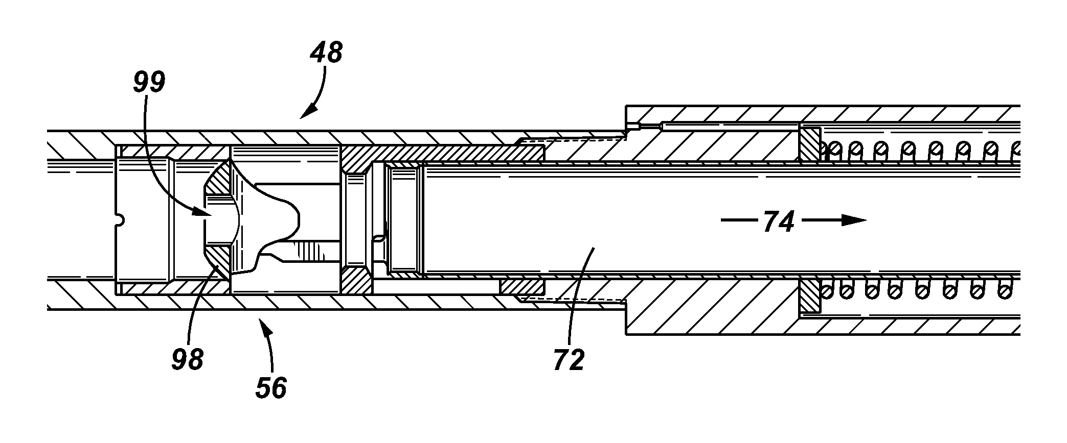
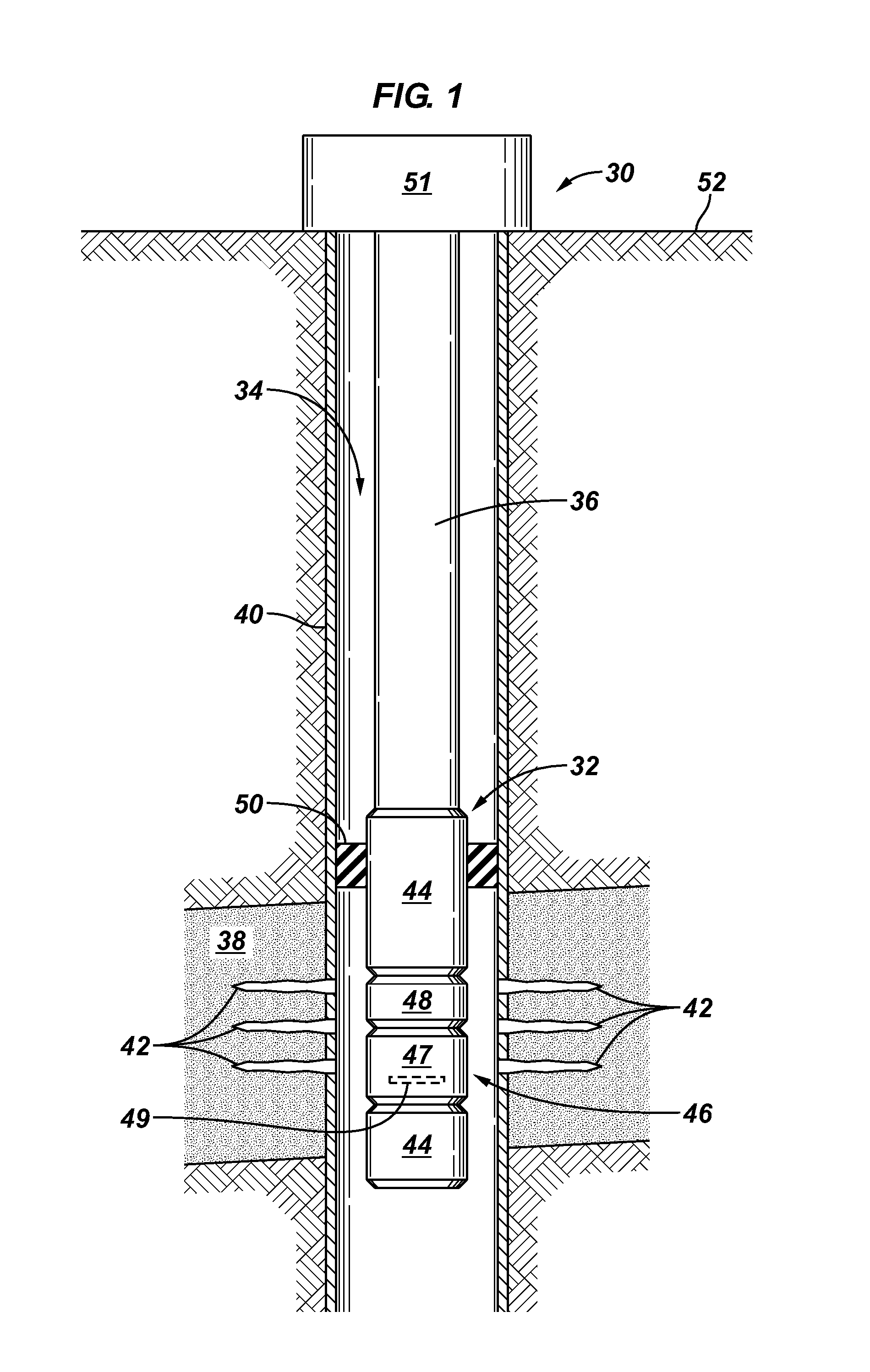
The present invention generally relates to a flow control system used to control flow in a wellbore. For example, the flow control system comprises a flow control device combined with a flow reduction mechanism for use in a variety of well related operations. The flow control system can be used in production and / or injection operations.

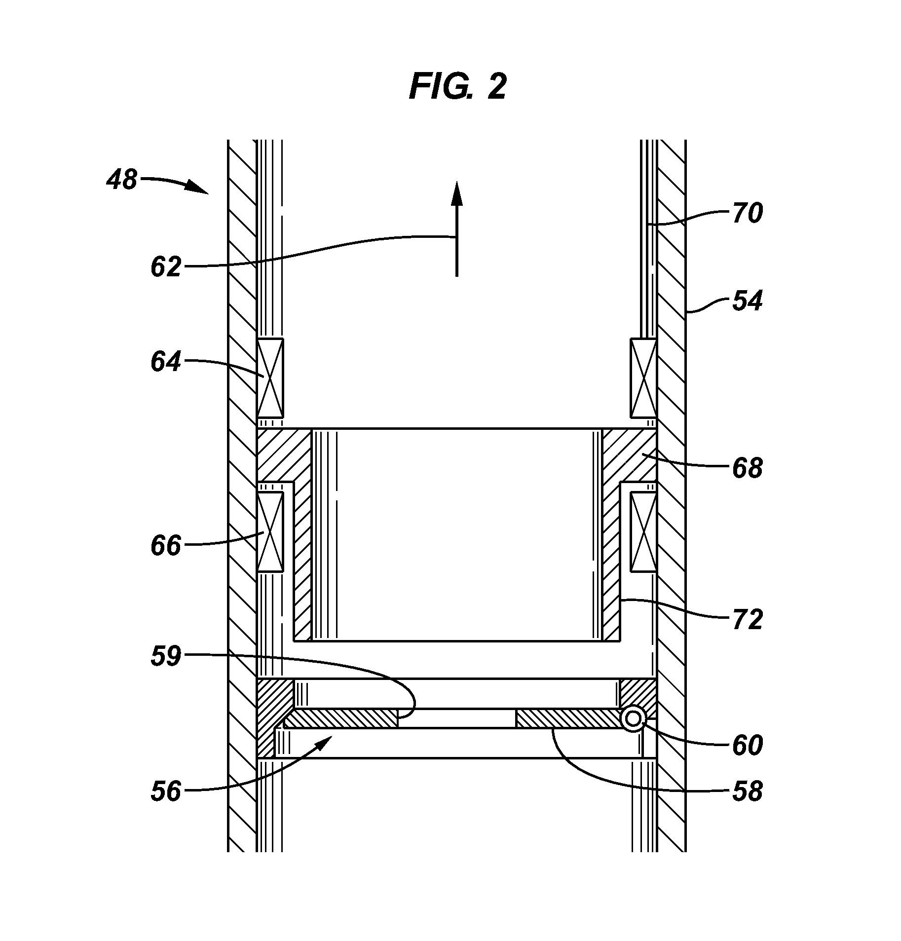
Generally, combining the flow restricting or flow reduction mechanism with the flow control device reduces potential loads acting on the flow control device which enhances the ability of the flow control device to close and seal effectively. In production applications, this allows higher production rates without ad...


PUM


Abstract

A technique enables control over flow in a wellbore with a flow control system. The flow control system combines a flow reduction mechanism with a flow control device, such as a valve. The flow reduction mechanism comprises a closure member which can be selectively moved between an unactuated and actuated position, allowing relatively greater flow through the flow control device in the unactuated position. The flow reduction mechanism actuates prior to or in conjunction with the flow control device to reduce flow and thus reduce the loading forces that would otherwise act against the flow control mechanism upon closure of the flow control device.

Description

BACKGROUNDIn many well related operations, appropriate well equipment is moved downhole to control fluid flow. For example, various completions are used to facilitate and control the flow of fluid in both production operations and injection operations. Valves are sometimes used to choke or otherwise control flow of fluid through the well equipment.In some applications, detrimental reverse flow can be a problem and valves have been used to prevent flow in the undesirable direction. Flapper valves, for example, have been used to enable flow through tubing in one direction while blocking flow in the opposite direction. However, flapper valves offer limited ability for adjustment to accommodate various procedures during a production and / or injection operation.For example, many subsurface safety valves utilize a flapper as a closure mechanism fitted within a body or housing member to enable control over fluid flow through a primary longitudinal bore upon an appropriate signal from a cont...

Claims


Application Information

Patent Timeline
Patent Type & Authority Applications(United States)
IPC IPC(8): E21B34/10
CPCE21B34/10E21B2034/005E21B2034/002E21B2200/04E21B2200/05Y10T137/7847
Inventor MAY, DWAYNEMCCALVIN, DAVIDGOUGHNOUR, PAUL GORDONBIDDICK, DAVID JAMESJOHNSTON, RUSSELL ALAN
Owner SCHLUMBERGER TECH CORP
Why Eureka
Try Eureka