Shaker conveyor with elliptical gear drive system

a technology of elliptical gear drive and conveyor, which is applied in the direction of conveyors, conveyors, jigging conveyors, etc., can solve the problems of material starting to move in the reverse direction before slipping, and achieves smooth, continuous and efficient forward linear movement of material, rapid acceleration and rapid deceleration

Active Publication Date: 2011-10-20
PAX PRODS
View PDF4 Cites 4 Cited by
  • Summary
  • Abstract
  • Description
  • Claims
  • Application Information

AI Technical Summary

Benefits of technology

[0004]The present invention is directed to an improved shaker conveyor which provides all of the advantages mentioned above including a compact unit which quickly mounts on a mechanical press and encloses an electric motor drive unit which is dependable in operation and effectively reciprocates a plurality of parallel spaced shaker trays with a rapid acceleration and a rapid deceleration at one end of the reciprocating stroke of the trays in order to provide a smooth, continuous and efficient forward linear movement of the material on the trays. The opposite end of the stroke is very low in acceleration and deceleration.
[0006]A rocker arm and link assembly is connected to the output shaft eccentrically of the axis of the output shaft to produce oscillation of the rocker arm and link assembly in response to rotation of the output shaft. The rocker arm and link assembly are connected to a carriage which supports the tray to reciprocate the tray and produce rapid acceleration and rapid deceleration at one end of the reciprocating stroke of the tray in order to produce smooth, continuous and efficient movement of the material on the tray. In another embodiment, multiple parallel trays are connected to an extended carriage having opposite end portions supported by carriage plates for reciprocating movement by linear bearings on parallel guide rails. The plates are connected by links to rocker arms mounted on a common shaft oscillated by a drive unit located between the carriage support plates.

Problems solved by technology

The slippage usually occurs after the tray has been reversed with the result that the material starts moving in the reverse direction before slipping.

Method used


Image

  • Shaker conveyor with elliptical gear drive system
  • Shaker conveyor with elliptical gear drive system
  • Shaker conveyor with elliptical gear drive system

Examples


Embodiment Construction

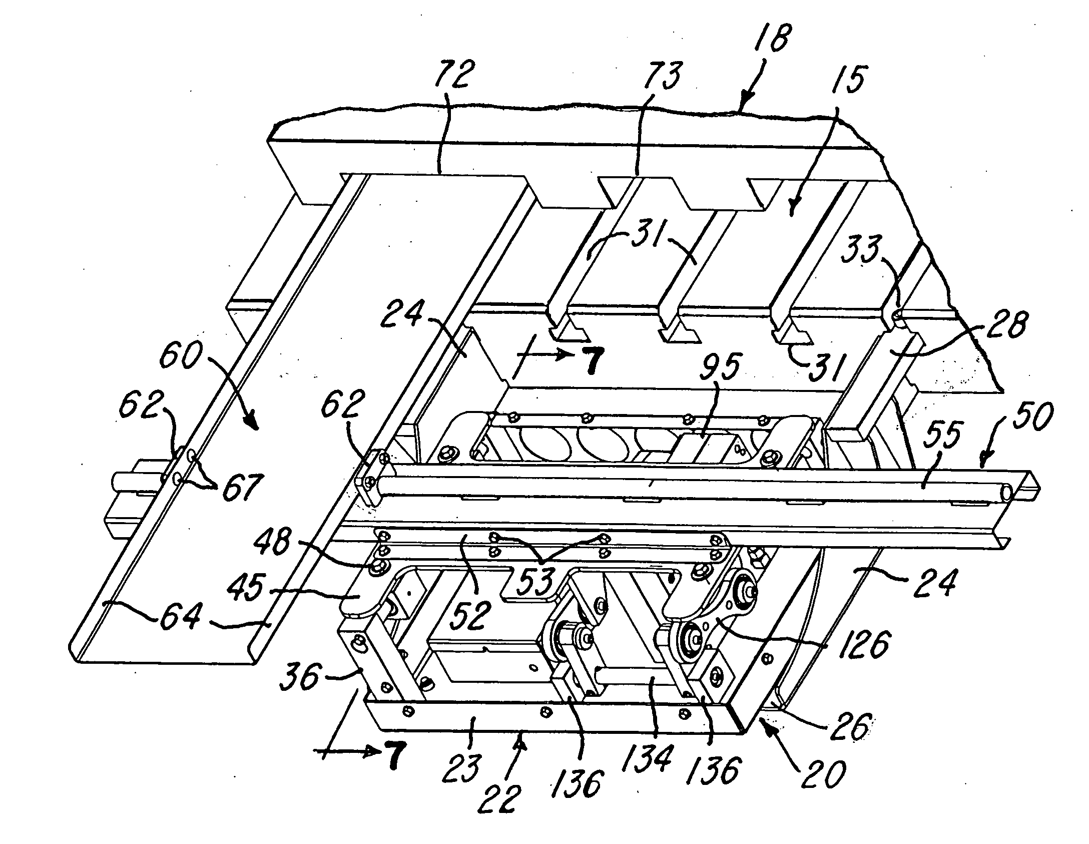
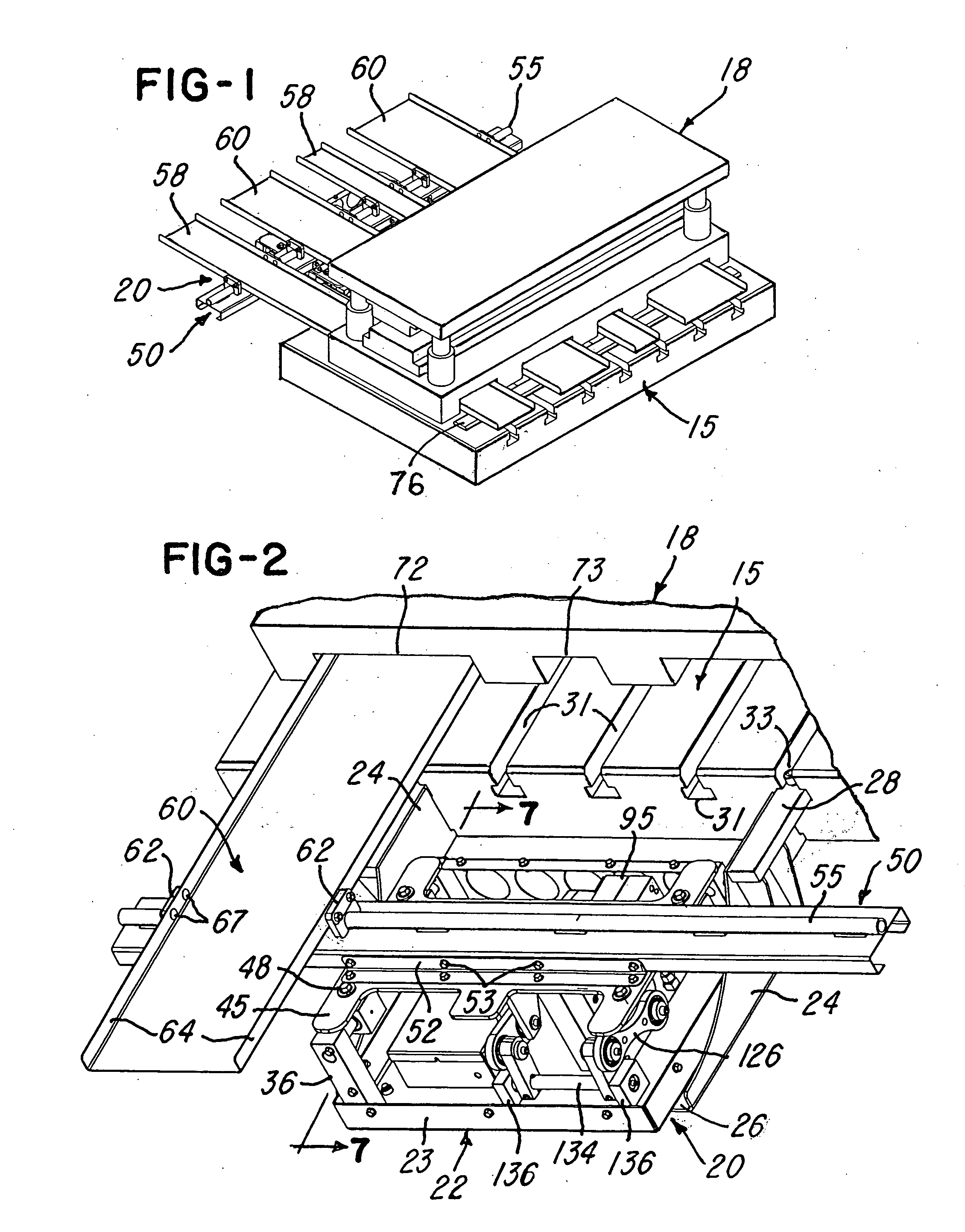
[0019]FIG. 1 shows a bolster plate 15 of a conventional mechanical press and on which is mounted a progressive die 18. The bolster plate 15 also supports a shaker conveyor system or unit 20 constructed in accordance with the invention. The unit 20 includes a bottom pan-shaped rectangular base plate 22 (FIG. 2) having upwardly projecting boarder flanges 23. The base plate is supported on opposite ends by a pair of angle end brackets 24 (FIG. 2) having bottom flanges 26 projecting under the base plate 22 and secured to the base plate. The upper edge portions of the end brackets 24 are secured to straight flat bars 28 which project into corresponding T-slots 31 in the bolster plate 15, and each bar 28 is secured to the plate 15 by a pair of jack screws 33 which force the bar upwardly against the undercut surfaces of the T-slot. This attachment provides for quickly attaching and removing the unit 20 to the press.

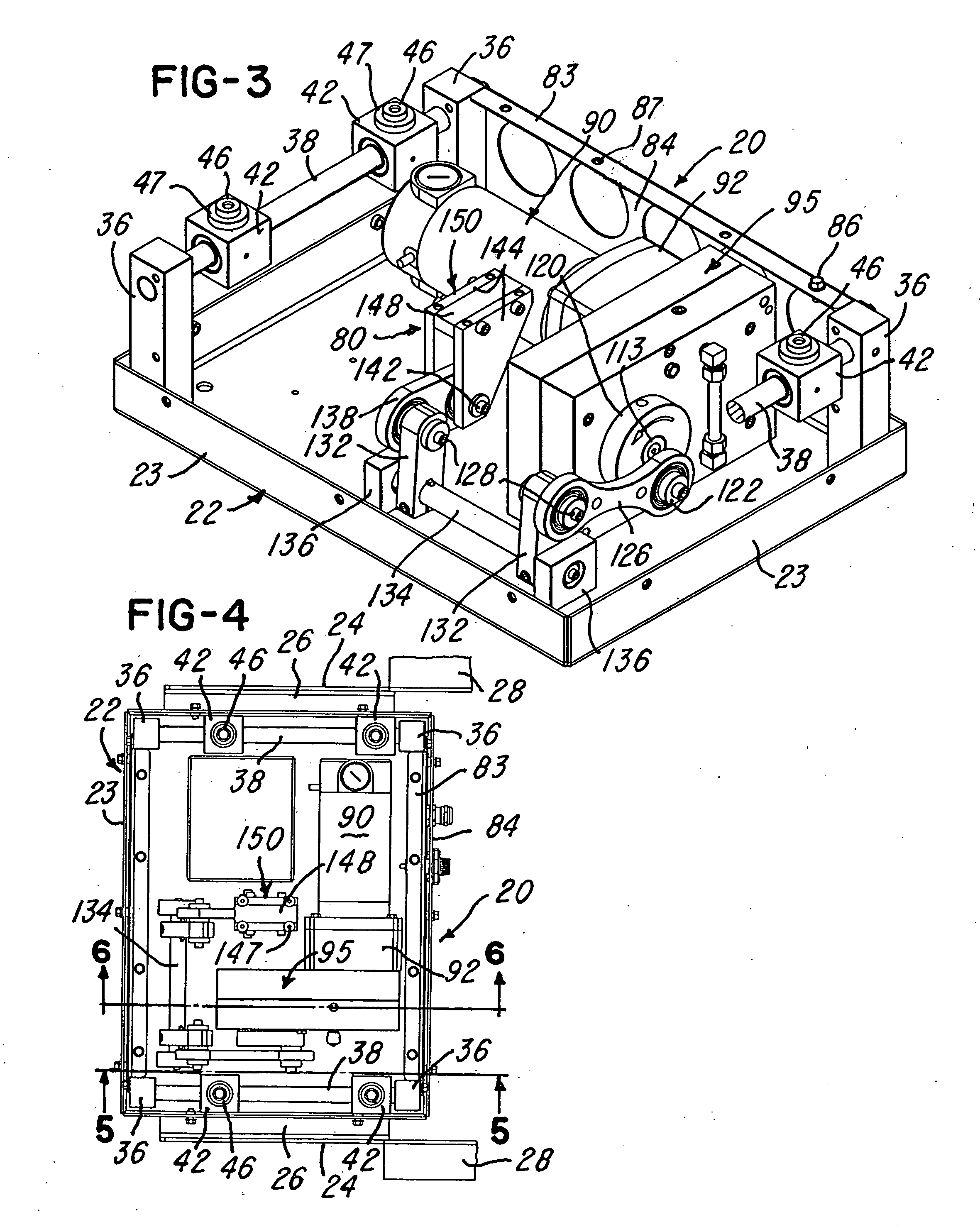
[0020]The shaker conveyor system or unit 20 has a set of four corner posts ...


PUM


Abstract

Scrap metal pieces are conveyed from a mechanical press by a shaker conveyor having horizontal and parallel spaced elongated trays supported for reciprocating movement by an elongated carriage positioned above a compact drive unit attached to and supported by the press. The drive unit includes an electric motor connected to rotate an elliptical input gear on an eccentric axis and in continuous mesh with an elliptical output gear eccentrically connected to an output shaft. A rocker arm and link assembly is eccentrically connected to the output shaft and oscillates a shaft connected to the carriage by one or more rocker arm and link assemblies for reciprocating the trays with rapid acceleration and rapid deceleration. The elliptical input and output gears are identical in size and have the same odd number of teeth, and in one embodiment, the drive unit is located between a set of rocker arm and link assemblies.

Description

RELATED APPLICATION[0001]This application is a continuation-in-part of application Ser. No. 12 / 590,647, filed Nov. 12, 2009.BACKGROUND OF THE INVENTION[0002]This invention relates to shaker conveyors of the type commonly used for transferring scrap pieces of metal from a mechanical press to a collection container and as disclosed, for example, in U.S. Pat. No. 6,415,912, No. 6,634,488 and in published patent applications No. 2007 / 0017783 and No. 2008 / 0245639. However, such shaker conveyors may also be progressively transferring other articles along a generally horizontal path. In such conveyors, one or more horizontal elongated trays are reciprocated at a frequency or speed and with a motion that the pieces or articles are progressively advanced along each tray. Shaker conveyors are commonly described as having a motion where the tray and the material to be conveyed move in one direction together and then the tray is rapidly moved in the opposite direction making the material slip r...

Claims


Application Information

Patent Timeline
Patent Type & Authority Applications(United States)
IPC IPC(8): B65G27/12
CPCB65G27/18B65G27/12
Inventor PAX, STEVEN J.
Owner PAX PRODS
Why Eureka
Try Eureka