Slat support assembly

a technology of support assembly and slats, which is applied in the direction of mechanical equipment, transportation and packaging, etc., can solve the problems of wing structure, inconvenient opening, and design restrictions on shape, and achieve the effect of reducing the overall weight of the assembly

a technology of support assembly and slats, which is applied in the direction of mechanical equipment, transportation and packaging, etc., can solve the problems of wing structure, inconvenient opening, and design restrictions on shape, and achieve the effect of reducing the overall weight of the assembly

US20110253832A1Inactive Publication Date: 2011-10-20AIRBUS OPERATIONS LTD

Image

  • Slat support assembly
  • Slat support assembly
  • Slat support assembly

Examples


Embodiment Construction

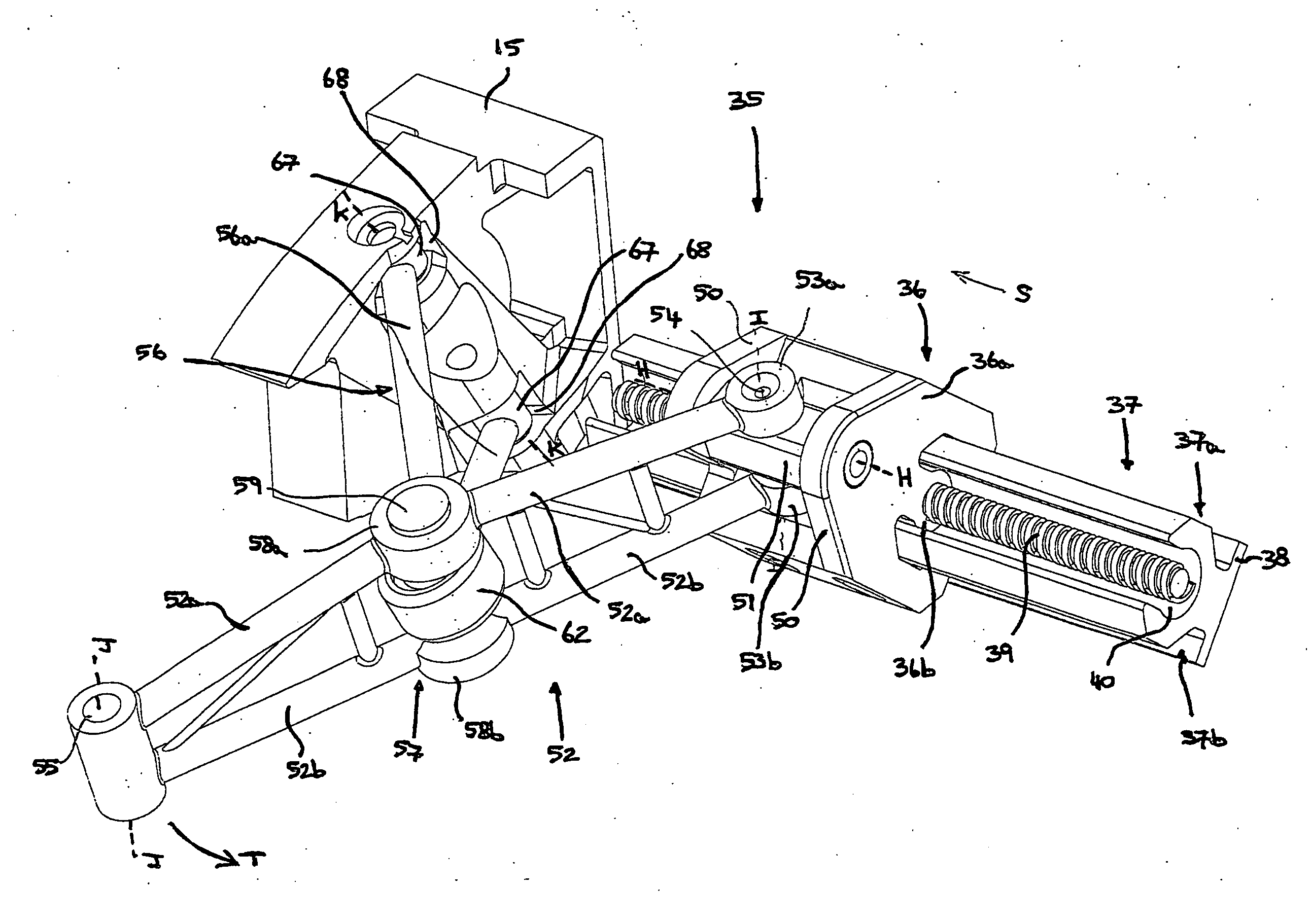
[0061]Referring primarily to FIG. 4, there is shown a slat support assembly 35 according to the present invention which employs a modified scissor mechanism similar that previously described. Fundamentally, the assembly of the present invention no longer relies on a slideable and rotatably mounted tube. Furthermore, the connection between the primary and secondary support arms has been modified.

[0062]Referring to FIGS. 4 to 8, the assembly 35 comprises a carriage 36 having a body 36a mounted on an elongate track 37. The track 37 is rigidly attached to the wing structure of an aircraft so that it remains stationary relative to the rib 15. The track 37 has a flange 38 that may be placed against part of the wing structure. Holes (not shown) may extend through the flange 38 to allow bolts or other conventional fasteners to be inserted therethrough to facilitate attachment of the track 37 to the wing structure. The track 37 also has a carriage mounting portion 37a attached to the flange ...


PUM


Abstract

A support assembly for deployment and retraction of an aero surface from an aircraft is disclosed. The assembly comprises a guide track, a primary support arm having one end coupled to a carriage mounted on the track such that the primary support arm is rotatable relative to the carriage about multiple axes, and a control arm having one end coupled to the primary support arm and a second end pivotably attachable to a fixed support forming part of the structure of the aircraft. The assembly being configured such that, when the carriage is driven along the guide track, the control arm causes the primary support arm to pivot about said multiple axes to deploy and / or retract an aero surface pivotally attached to an opposite end of the primary support member along an arcuate path.

Description

INTRODUCTION[0001]The present invention relates to a support assembly for supporting the slats on the leading edge of an aircraft wing and which is operable to deploy, and retract, the slats from the wing to control lift during flight. The invention also relates to an aircraft wing comprising at least one slat attached to a leading edge of the wing using the support assembly of the invention.BACKGROUND[0002]Aircraft need to produce varying levels of lift for take-off, landing and cruise. A combination of wing leading and trailing edge devices are used to control the wing coefficient of lift. The leading edge device is known as a slat. On larger aircraft there may be several slats spaced along the wing edge. During normal flight the slats are retracted against the leading edge of the wing. However, during take-off and landing they are deployed forwardly of the wing so as to vary the airflow across and under the wing surfaces. The slats usually follow an arcuate or curved path between...

Claims


Application Information

Patent Timeline
20 Oct 2011
Publication
US20110253832A1
IPC
B64C13/28; F16H25/20; F16H21/44
CPC
B64C9/02; B64C9/22; Y10T74/18992; Y10T74/18648; Y02T50/44; Y02T50/40
Inventors
WILDMAN, ERIC; PARKER, SIMON JOHN