Supercharge Your Innovation With Domain-Expert AI Agents!

Railway Track And Switch Weather Protection Barrier System

Active Publication Date: 2011-10-20
OSBORN LLC
View PDF2 Cites 12 Cited by
  • Summary
  • Abstract
  • Description
  • Claims
  • Application Information

AI Technical Summary

Benefits of technology

[0013]The present invention is directed to a barrier system for railroad and railway tracks used to help keep precipitation, including snow and ice, away from one or more track rails in the vicinity of a switch or turnout. The barrier system includes a barrier having an upper edge with deflecting elements movable relative one another located adjacent a head of a track rail within a wash zone of flowing air created by a train traveling along the tracks along the barrier. The upper barrier edge is part of a deflector inclined toward the adjacent rail that deflects wind and precipitation away from the rail helping to prevent snow and ice accumulation between the barrier and adjacent rail while also helping reduce heat loss where a portion of a switch clearing system, such as ductwork and / or a heating element, is located between the barrier and adjacent rail. Inclining the deflector toward the rail allows its upper edge to be positioned very closely to the rail while minimizing the amount of direct contact with any railway vehicle wheel and any high-railer or road-railer tire. The barrier includes a skirt that can be part of the deflector that extends downwardly conforming to the contour of the underlying railway bed and ties or sleepers supported by the bed.

Problems solved by technology

While switch clearing systems are in widespread use, they are not foolproof.
There are times however, when the control system can malfunction, such as when a precipitation gauge malfunctions during periods of high winds or excessive precipitation accumulation.
There are times when weather conditions are so extreme that snow and ice buildup despite switch clearing system operation.
Unfortunately, these conventional barrier systems possess many drawbacks.
Since their barriers are of solid, imperforate or hard shell construction, they cannot be placed too close to the top or head of any rail to avoid directly contacting part of a train or rail maintenance vehicle traveling on the rails, which can significantly limit their effectiveness.
The tires of such a rail maintenance vehicle can come into contact with barriers as the vehicle travels along the rails, which can dislodge or even damage them.
The same can occur with chained together semi-trailers riding on bogies or wheelsets in a “roadrailer” configuration being pulled by a locomotive that have tires that hang downwardly very close to the rails, as this also limits how high and how close to the rails that conventional barriers can be located.
In addition, high winds combined with the repeated cycling caused by the wash from trains passing through also can dislodge and even damage such barriers, which not only can adversely impact switch clearing system operation, it can also undesirably result in a dislodged or damaged barrier coming into contact with part of the train at some point further damaging or even destroying them.
Unfortunately, the large spacing that must be provided results in considerable heat produced by rail heater operation being lost dramatically reducing the effectiveness of these types of switch clearing systems, particularly in severe or extreme weather conditions.
Conventional barrier systems suffer from other drawbacks as well.
Despite being so far away from the top of any rail that rail heater heat loss cannot be prevented, such barriers are usually still located close enough to hinder track inspection and repair.
Where inspection or repair is required, removal is undesirably time consuming and labor intensive.
In some instances, their use is seasonal requiring them to be removed and typically stored in large, space consuming racks.
Accordingly, it has been found that locations utilizing these types of barrier systems have relatively high operating and maintenance costs.
Though conducive for rail inspection, its perpendicular vertical orientation and large distance from the adjacent rail allows snow and ice accumulation to occur between the brush strip and rail limiting its functionality as a barrier system.
Finally, the spacing is so great from the rail that the brush strip does nothing to prevent heat loss during rail heater operation.

Method used


Image

  • Railway Track And Switch Weather Protection Barrier System
  • Railway Track And Switch Weather Protection Barrier System
  • Railway Track And Switch Weather Protection Barrier System

Examples


Embodiment Construction

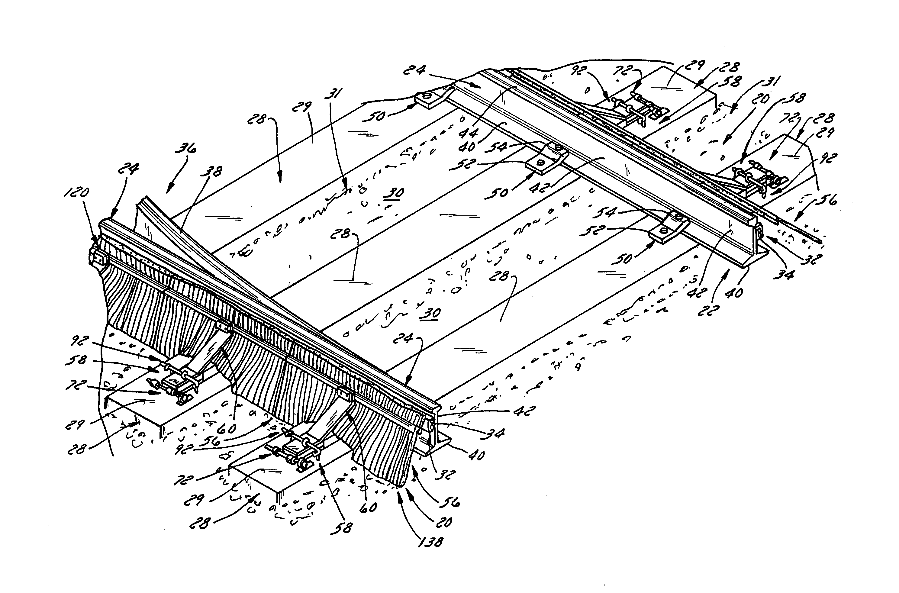
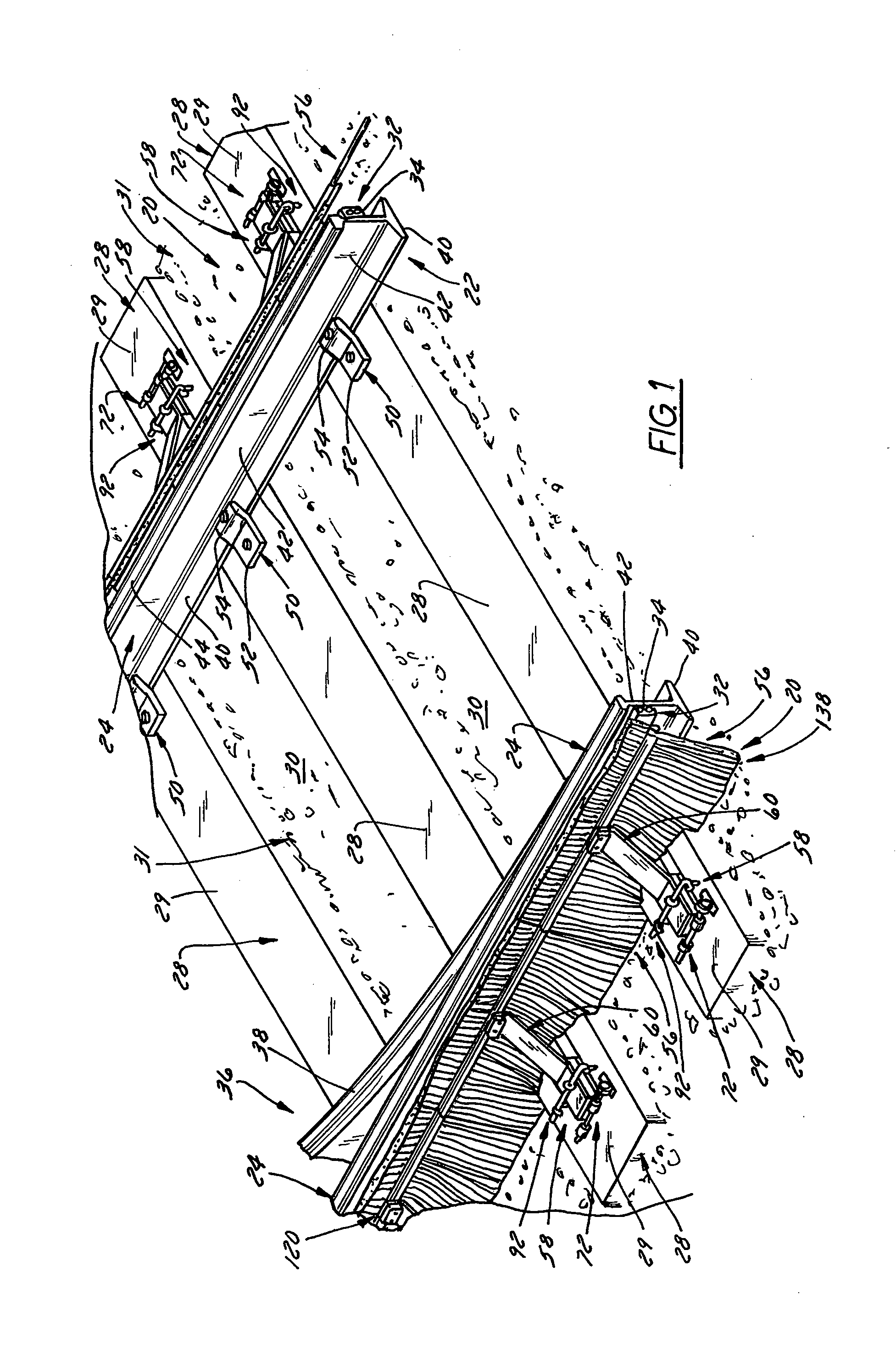
[0036]Referring now to the drawings, and initially to FIG. 1, a pair of weather protecting barrier systems 20 for use with railroad tracks 22 according to the present invention is illustrated with each barrier system 20 extending alongside a corresponding rail 24 of a set of railroad or railway tracks 22 supported on transversely extending railroad ties or sleepers 28 carried by a bed 30 of gravel or rock. Each barrier system 20 typically is located alongside a switch clearing system 32, such as one employing a switch or rail heater 34, used to help keep a switch or turnout 36 operable in cold weather. Such a switch or turnout 36 typically includes one or more switch rails 38 movable relative to a set of fixed rails 24 enabling a train or railway cars of a train to be switched from one set of tracks to another set of tracks. While the switch clearing system 32 shown in FIG. 1 employs a switch or rail heater 34 attached to each rail 24 between the barrier system 20 and adjacent rail ...


PUM


Abstract

A railway track barrier system that includes a barrier extending along a rail adjacent a switch having an upper edge adjacent a rail head disposed within a wash zone thereof formed of deflector elements movable relative to one another permitting railway vehicle wheel and wash contact during train passage without barrier dislodgement or damage. The barrier is formed of a deflector acutely inclined toward the head and a downwardly extending skirt that conforms to uneven railway bed and tie surfaces. A preferred barrier is formed of oppositely extending brushes removably attached to a mounting bracket. The bracket can be attached to a hinge assembly that releasably latches the barrier in an operating position and that can be unlatched permitting the barrier to be swung away from the rail to an inspection position. A hinge pin with a manually graspable handle can be removed to detach the barrier for storage.

Description

CROSS-REFERENCE TO RELATED APPLICATION[0001]This application claims the benefit of priority from U.S. Provisional Patent Application Ser. No. 61 / 326,012 filed on Apr. 20, 2010 and entitled Railway Track and Switch Weather Protection Brush Assembly, the entirety of which is hereby incorporated by express reference thereto.FIELD OF THE INVENTION[0002]The present invention relates to an assembly for providing a weather barrier alongside the rails of a railway track and more particularly to a barrier system that helps protect rails and switch clearing systems adjacent the rails in the vicinity of a switch or turnout.BACKGROUND[0003]Track switches or turnouts are found at various locations along railroad or railway tracks that typically include one or more switching rails that are movable relative to fixed track rails between one position that allows a train or cars of the train to continue traveling along the same set of tracks or another position that switches the train or cars of the ...

Claims


Application Information

Patent Timeline
IPC IPC(8): E01B7/00
CPCE01B19/00E01B7/20Y02A30/30
Inventor FERRYMAN, ROGERDUBAY, PAUL R.
Owner OSBORN LLC
Features
  • R&D
  • Intellectual Property
  • Life Sciences
  • Materials
  • Tech Scout
  • Unparalleled Data Quality
  • Higher Quality Content
  • 60% Fewer Hallucinations
Learn More