
Connectors for LED strip lighting

Inactive Publication Date: 2011-10-20
VIRGINIA OPTOELECTRONICS
View PDF22 Cites 34 Cited by
  • Summary
  • Abstract
  • Description
  • Claims
  • Application Information

AI Technical Summary

Benefits of technology

[0007]Embodiments of the present invention provide connectors for flexible or rigid strip lighting devices that can be combined and conveniently interconnected with the strip lighting to form modular lighting systems. The connectors can be used with waterproof, water-resistant, or non-waterproof lighting strips.
[0009]Connectors of the invention can comprise two identical sockets joined together at their electrical contacts to form a double connector. In this manner, the same components that are used for the lighting strip sockets can also be used for the connectors thus achieving simplicity in manufacturing, as no special socket components are required. For 3-way and 4-way type sockets, three or four, respectively, identical sockets can be incorporated with a PCB and circuit to for the complex connector. Again, by using standard socket components, a manufacturer can easily make the connectors from existing parts instead of creating another part that cannot be used with other components, such as the lighting strips or connections with a power source through wire leads.

Problems solved by technology

Although lighting systems have been somewhat successful, the known lighting systems have encountered certain problems.
One known problem is the excessive number of components required to make such lighting systems.
Another problem relates to the fragile nature of such lighting systems.
Often lighting systems must be individually crafted which increases the purchasing price associated with such lighting systems.
Another problem with known lighting systems relates to the lack of convenient interconnectable components of individual lighting sections and the lack of easily removable and securely fit interconnections.

Method used


Image

  • Connectors for LED strip lighting
  • Connectors for LED strip lighting
  • Connectors for LED strip lighting

Examples


Embodiment Construction

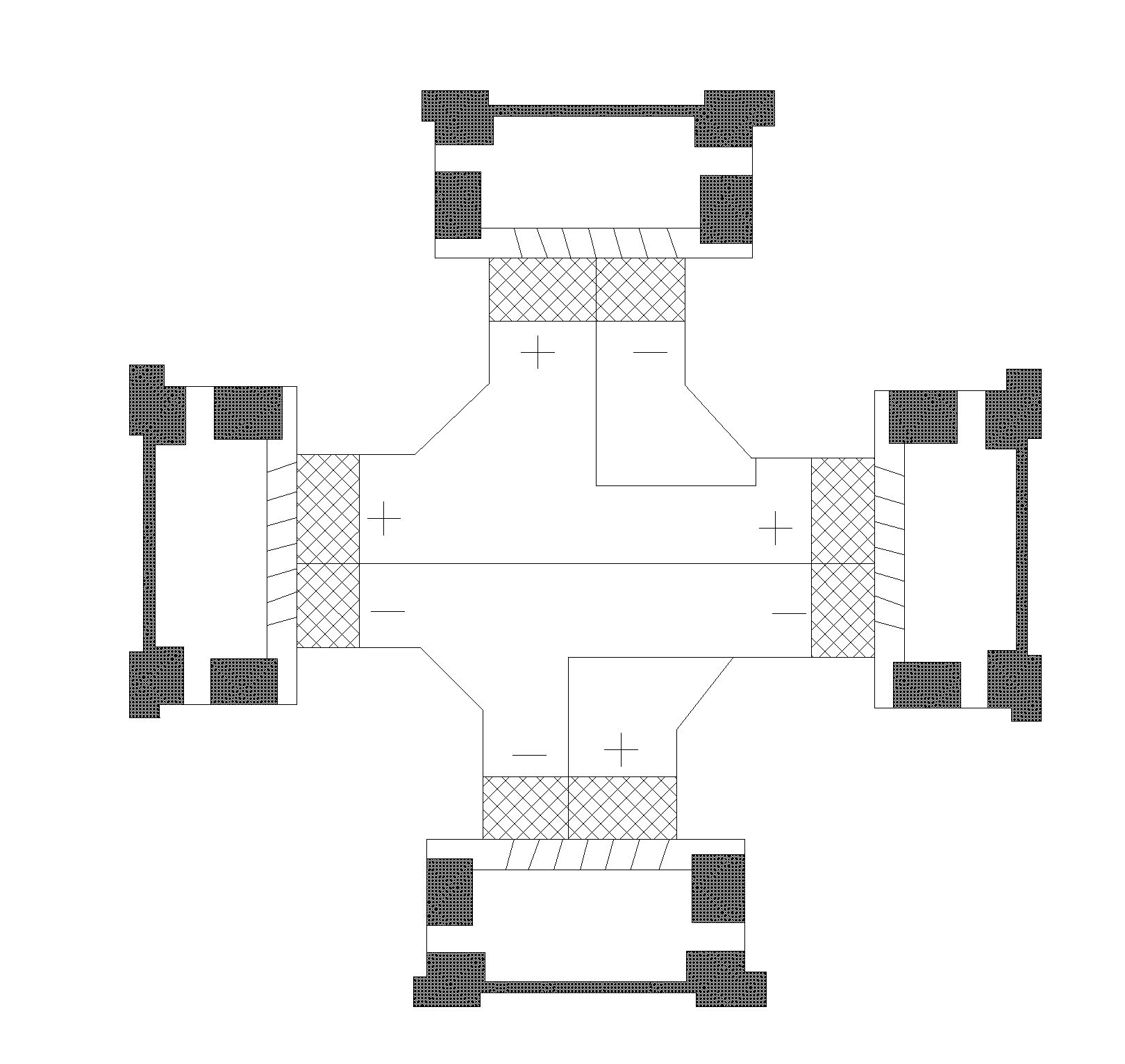
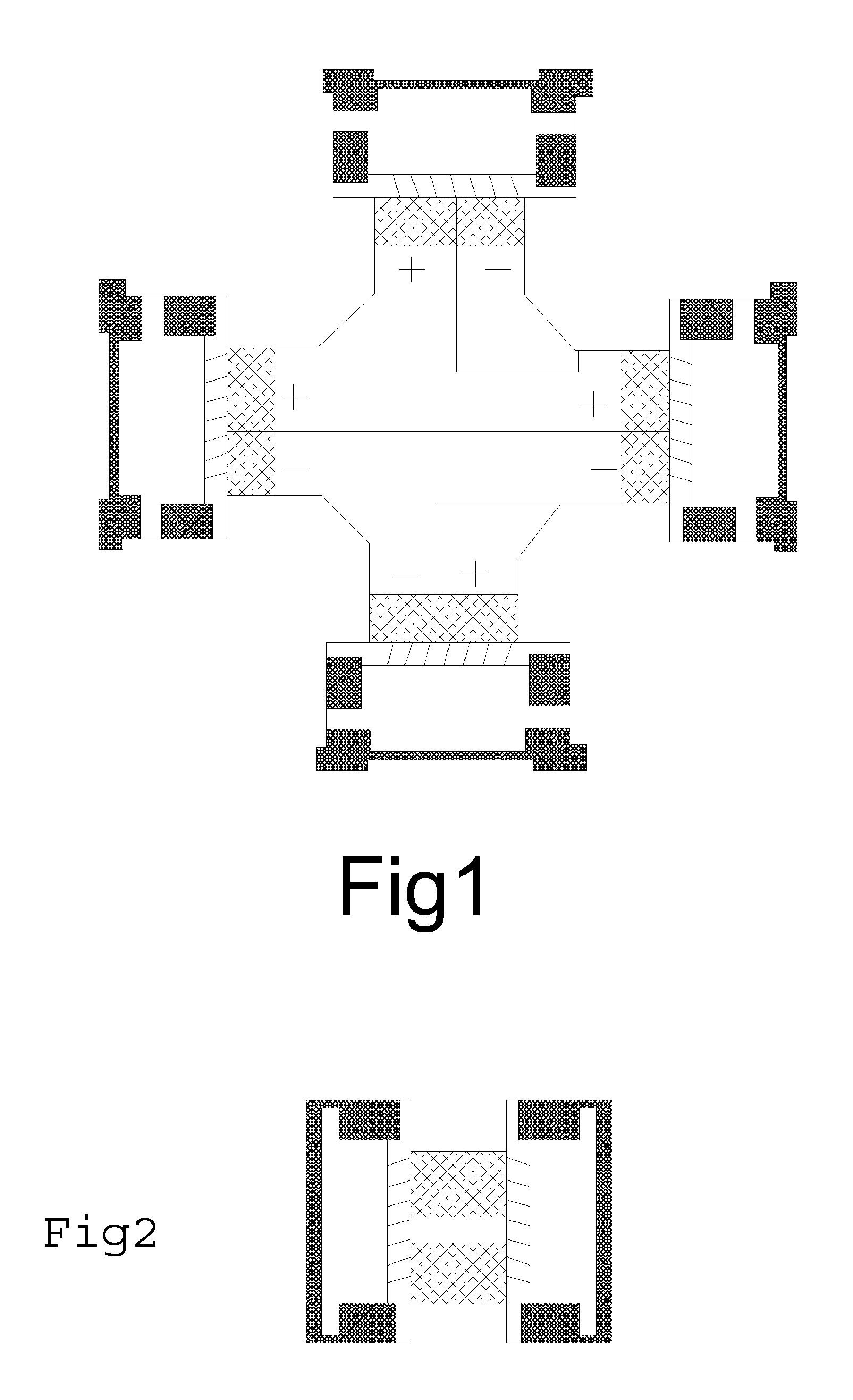
[0039]In accordance with embodiments of the present invention, provided are various connector assemblies for lighting strips and lighting strip systems with connector assemblies. More particularly, the present invention relates to modular lighting systems, which provide for mechanical (e.g., physical) and electrical interconnection of multiple lighting strip devices to form lighting systems.

[0040]One of the many potential advantages of the connectors of the present invention, only some of which are discussed herein, is that the connectors may be used with a variety of lighting strips that can be combined and conveniently interconnected with the strip lighting to form modular lighting systems. In some embodiments, the connectors may be used with rigid lighting strips, flexible lighting strips, water-resistant, waterproof, or non-waterproof, and any combination thereof.

[0041]In certain embodiments, the connectors may also be used with PCBs that can be combined and conveniently interco...


PUM


Abstract

The present invention is directed to connectors for lighting strips. More particularly, the present invention relates to modular lighting systems, which provide for physical and electrical interconnection of multiple lighting strip devices to form lighting systems. In an embodiment, the present invention provides a connector assembly for modular lighting strips comprising: two or more integrally-formed plugs or sockets joined together in a manner to provide for physical and electrical connection with two or more lighting strips comprising a non-conductive substrate strip with an electrical circuit; a plurality of light sources operably connected to the electrical circuit; and a plug or socket integrally formed at opposing ends of the substrate strip; wherein the plugs and sockets provide for removable, friction-fit, and electrical interconnection of two or more circuits of the lighting strips.

Description

CROSS-REFERENCE TO RELATED APPLICATIONS[0001]This application claims priority to and the benefit of the filing date of U.S. Provisional Patent Application No. 61 / 333,806, filed on May 12, 2010; and this application is a Continuation-in-Part of U.S. application Ser. No. 12 / 975,112, filed on Dec. 21, 2010, which claims priority to and the benefit of the filing date of U.S. Application Ser. No. 61 / 288,815, filed on Dec. 21, 2009, which CIP is a Continuation-in-Part of U.S. application Ser. No. 12 / 499,306, filed on Jul. 8, 2009, which claims priority to and the benefit of the filing date of U.S. Application Ser. No. 61 / 079,042, filed on Jul. 8, 2008, the disclosures of each of which are hereby incorporated by reference herein in their entireties.BACKGROUND OF THE INVENTION[0002]1. Field of the Invention[0003]The present invention relates to connectors for lighting strips, and more particularly for modular lighting systems, which provide for physical and electrical interconnection of mul...

Claims


Application Information

Patent Timeline
IPC IPC(8): F21S4/00H01R12/71
CPCF21S2/005F21V23/06H01R12/7076H01R13/7175F21S4/20
Inventor LI, QING (CHARLES)
Owner VIRGINIA OPTOELECTRONICS
Features
  • Generate Ideas
  • Intellectual Property
  • Life Sciences
  • Materials
  • Tech Scout
  • Unparalleled Data Quality
  • Higher Quality Content
  • 60% Fewer Hallucinations
Learn More