Semicircular inversed offset scanning for enlarged field of view 3D

a scanning and inverse offset technology, applied in tomography, applications, instruments, etc., can solve the problem of difficult to meet requirements

Inactive Publication Date: 2011-10-20
KONINKLIJKE PHILIPS ELECTRONICS NV
View PDF3 Cites 21 Cited by
  • Summary
  • Abstract
  • Description
  • Claims
  • Application Information

AI Technical Summary

Benefits of technology

[0032]In another aspect of the embodiment, the source is configured to be adjusted from a centered source position according to the detector displacement. The said source adjustment prevents radiation on regions which are not detected during detector offset positions.
[0033]According to yet another aspect a control device is prevented which is configured to actuating means for laterally displacing a radiation detector from a position with centered detector geometry with a centered transverse field of view to a first offset position and from the first offset position to a

Problems solved by technology

The reconstruction of 360 degree+offset detector scanners, using the standard “modified Feldkamp technique”, however is found to suffer from complications that are not present in the centered detector geometry.
This requirement is very difficult to meet because x-

Method used


Image

  • Semicircular inversed offset scanning for enlarged field of view 3D
  • Semicircular inversed offset scanning for enlarged field of view 3D
  • Semicircular inversed offset scanning for enlarged field of view 3D

Examples


Embodiment Construction

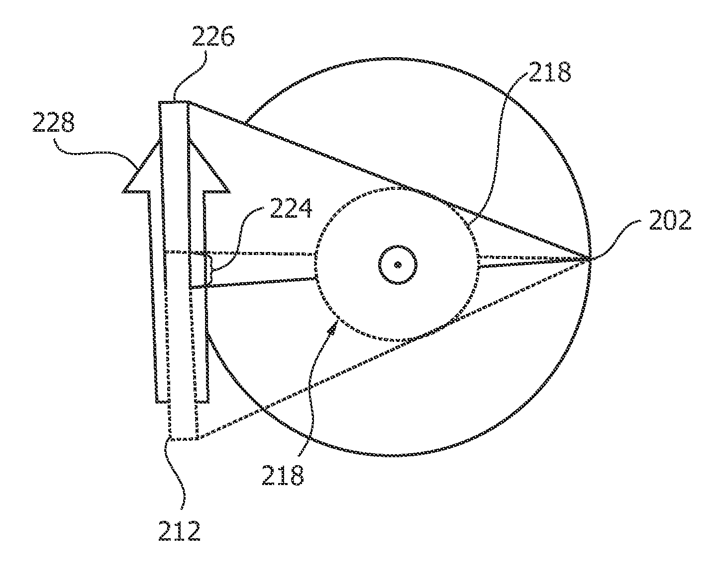
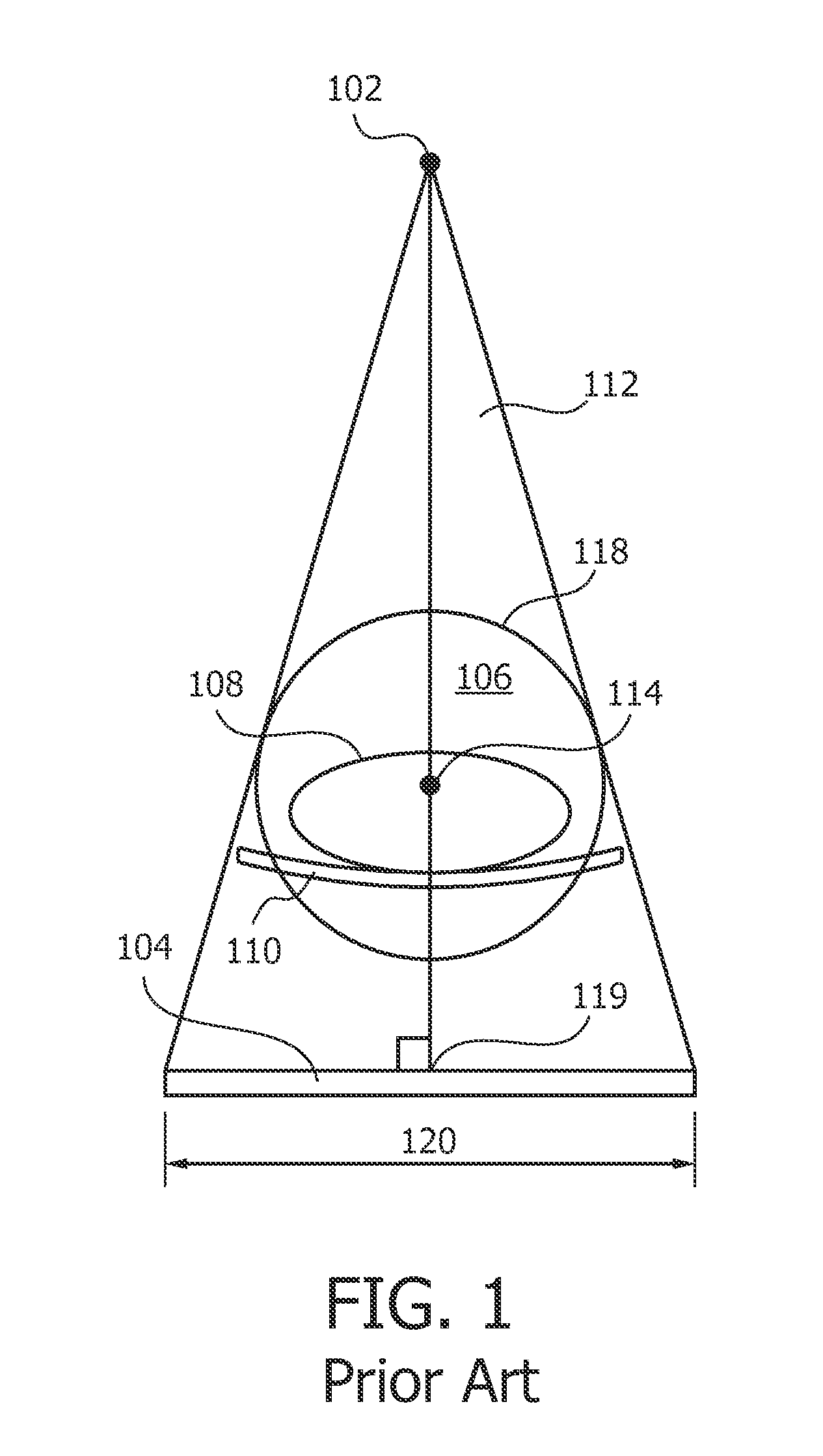
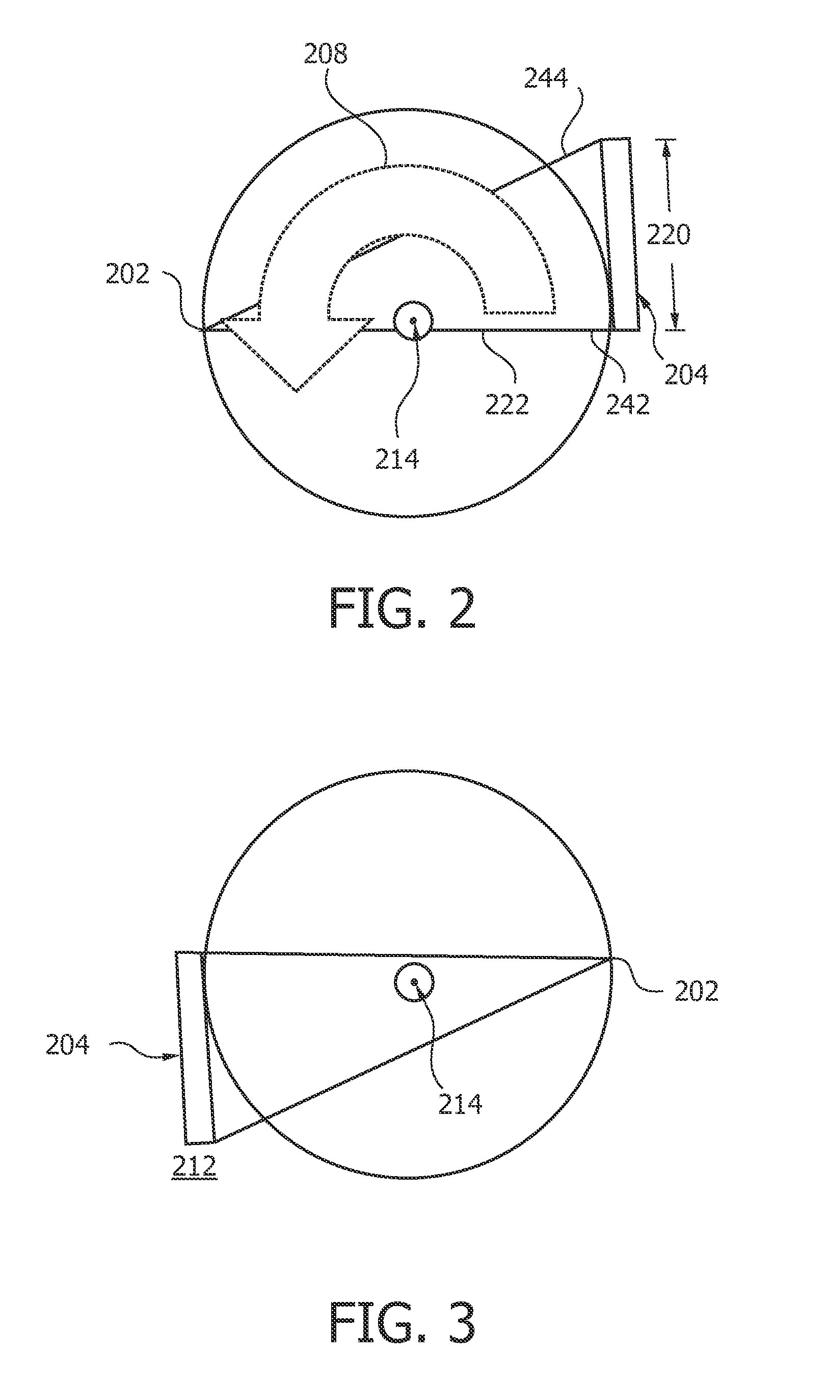
[0043]Relative to a full beam geometry, the detector 204 of an imaging system shown in FIG. 2 is shifted in a transverse direction by approximately one-half its transverse dimension or width 120. A ray or projection 222 with a small distance to the center of rotation 214 is perpendicular to the plane of the detector 204. At a given projection angle, the detector 204 detects radiation which has traversed approximately one-half the transverse FOV 218 shown in FIG. 4 (note that an overlap or transition region 224 ensures that projection data is acquired at a central region of the transverse FOV 218). While the half beam acquisition geometry achieves a relatively larger transverse FOV relative to the full beam geometry shown in the embodiment of FIG. 1, complete angular sampling of the transverse FOV requires that data be collected over an angular range of approximately 360°. The computed tomography method uses a X-radiation source 202, mounted with the detector 204 on a support not sho...


PUM


Abstract

A computed tomography acquisition method, an imaging system, a computer readable medium provides laterally displacing a radiation detector (204) from a position with centered detector geometry with a centered transverse field of view to a first offset position (212); emitting first radiation by the radiation source (202), detecting the first radiation by the radiation detector (204) and acquiring projection data indicative of the first radiation; rotating the support around the rotational axis (214) by 180°; emitting second radiation by the radiation source (202), detecting the second radiation by the radiation detector (204) and acquiring projection data indicative of the second radiation; displacing the radiation detector (204) from the first offset position to a second offset position (226), with opposite direction and double length of the first displacement (a); emitting third radiation by the radiation source (202), detecting the third radiation by the radiation detector (204) and acquiring projection data indicative of the third radiation; rotating the support around the rotational axis (214) by 180°; and emitting fourth radiation by the radiation source (202), detecting the fourth radiation by the radiation detector (204) and acquiring projection data indicative of the fourth radiation.

Description

FIELD OF THE INVENTION[0001]The present application relates to a method used in computed tomography (CT) and an X-ray CT apparatus. It finds particular application to x-ray CT for medical applications. It also finds application to article and security inspection, non-destructive testing, pre-clinical imaging, and other situations in which CT data can provide useful information about the structure or function of an object. Further, the present application relates to an imaging system, e.g. an X-ray imaging system, precisely a C-arm-system, a control device, configured to actuating means for displacing a radiation detector, a computer readable medium and a program element associated with said method.BACKGROUND OF THE INVENTION[0002]One area in which CT imaging systems have gained widespread acceptance is in medicine, where. CT scanners are widely used by radiologists and other medical professionals in connection with the diagnosis and treatment of disease. The relatively recent adopti...

Claims


Application Information

Patent Timeline
IPC IPC(8): A61B6/03
CPCA61B6/032A61B6/4014A61B6/4233A61B6/508A61B6/4441A61B6/4452A61B6/4435
Inventor NOORDHOEK, NICOLAAS JAN
Owner KONINKLIJKE PHILIPS ELECTRONICS NV
Why Eureka
Try Eureka