
Microfluidic device using microfluidic chip and microfluidic device using biomolecule microarray chip

a microfluidic chip and microfluidic chip technology, applied in the direction of positive displacement liquid engine, slide valve, material analysis, etc., can solve the problems of requiring less manual processes and limited application range of disk-type microfluidic devices, and achieve the effect of reducing the number of manual processes required for experiments or diagnosis using microarray chips

Active Publication Date: 2011-10-20
PRECISIONBIOSENSOR INC
View PDF3 Cites 0 Cited by
  • Summary
  • Abstract
  • Description
  • Claims
  • Application Information

AI Technical Summary

Benefits of technology

[0009]The present invention provides a microfluidic device using a microfluidic chip. In the microfluidic device, operations using various microfluidic chips formed in a platform can be automatically performed. According to the present invention, various kinds of biomolecule microarray chips can be used, and at the same time, the number of manual processes required for experiments or diagnosis using a microarray chip can be reduced significantly.

Problems solved by technology

However, the application range of the disk-type microfluidic devices is limited.
US 2002 / 0177144 titled “Detection and / or quantification of a target molecule by a binding with a capture molecule fixed on the surface of a disk.” However, there is still a need to develop a microfluidic device efficiently using various biomolecule microarray chips, requiring less manual processes to be performed, having a short operating time, and generating fewer errors in test results using the device.

Method used


Image

  • Microfluidic device using microfluidic chip and microfluidic device using biomolecule microarray chip
  • Microfluidic device using microfluidic chip and microfluidic device using biomolecule microarray chip
  • Microfluidic device using microfluidic chip and microfluidic device using biomolecule microarray chip

Examples


Embodiment Construction

[0040]The present invention will now be described more fully with reference to the accompanying drawings, in which exemplary embodiments of the invention are shown. In the drawings, like designation numbers denote like elements. The structures of chambers and channels illustrated in the drawings may be simplified, and enlarged or shirked. The term “micro-” used in a micro chip or a microfluidic device is used to only have the opposite meaning to the term “macro-,” and is not limited to a unit of micro.

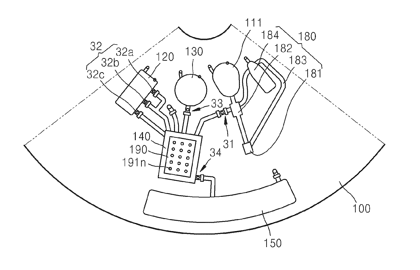
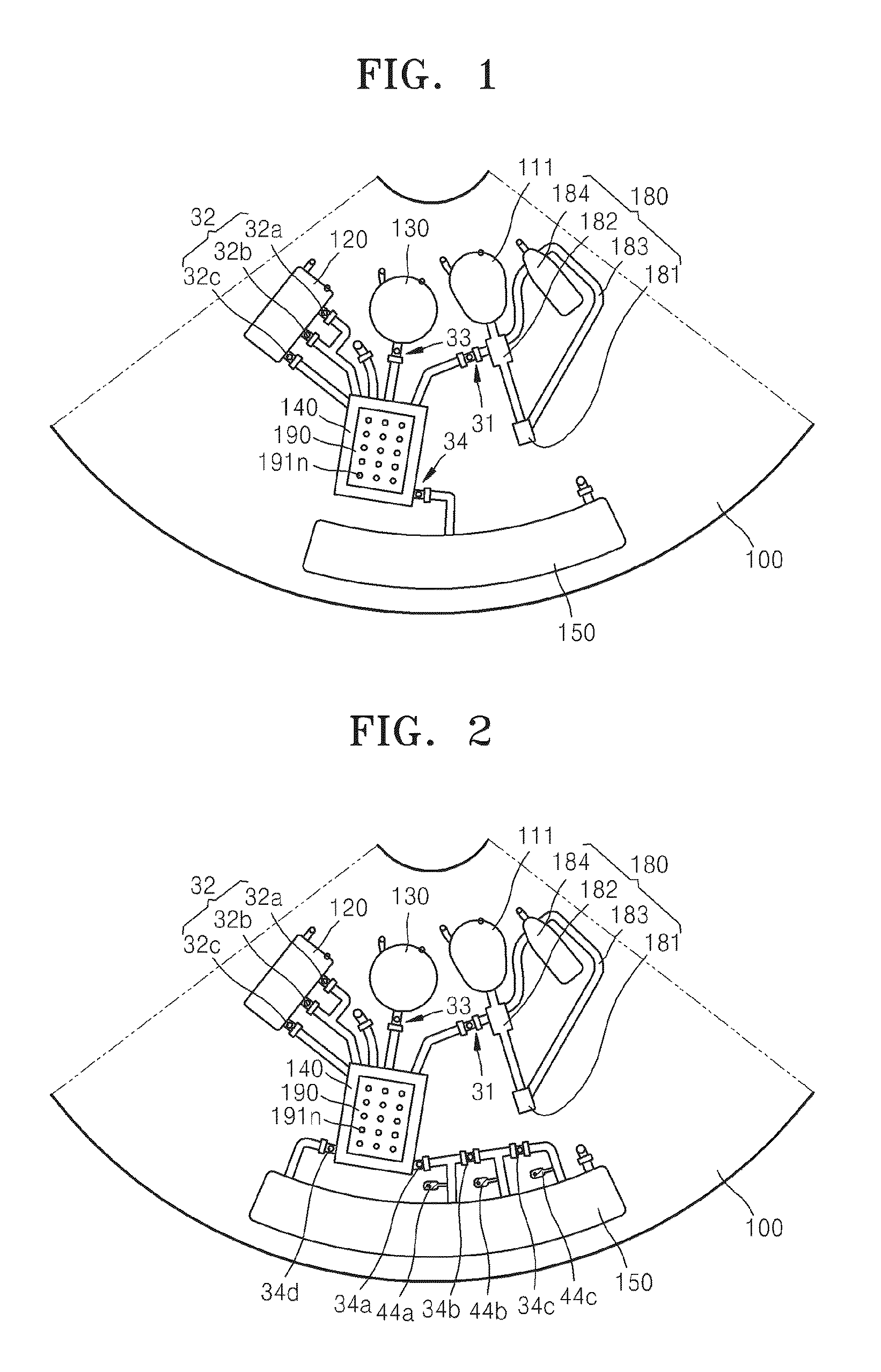
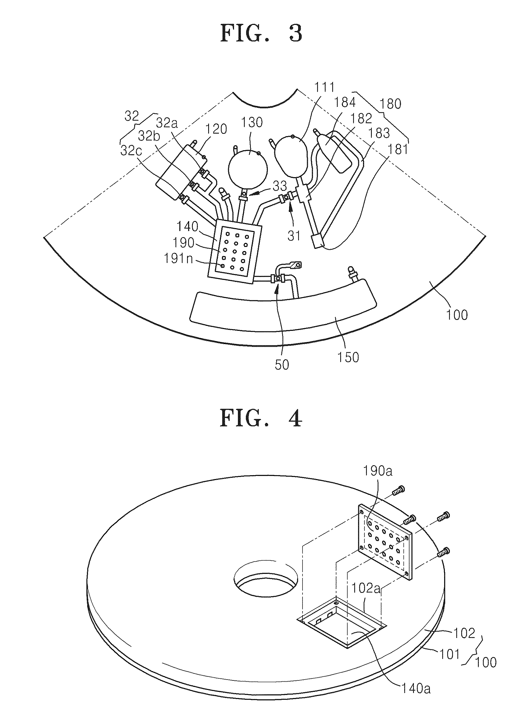
[0041]FIG. 1 is a plan view of a disk-type microfluidic device according to an exemplary embodiment of the present invention. According to the current exemplary embodiment, a microfluidic structure including a plurality of chambers 111, 120, 130, 140, and 150, channels (shown but not denoted with designated numbers) connecting the chambers to each other, and a plurality of valves 31, 32, and 33, and 34 controlling the flow of fluids through the channels is formed in a disk-type platfor...


PUM


Abstract

Disclosed is a microfluidic device including a microfluidic structure formed in a platform in which various examinations, such as an immune serum examination, can be automatically performed using the biomolecule microarray chip. The biomolecule microarray chip-type microfluidic device using a biomolecule microarray chip comprises: a platform which is rotatable; a microfluidic structure disposed in the platform, comprising: a plurality of chambers; a plurality of channels connecting the chambers each other; and a plurality of valves controlling flow of fluids through the channels, wherein the microfluidic structure controls flow of a fluid sample using rotation of the platform and the valves; and a biomolecule microarray chip mounted in the platform such that biomolecule capture probes bound to the biomolecule microarray chip contact the fluid sample in the microfluidic structure.

Description

CROSS-REFERENCE TO RELATED PATENT APPLICATIONS[0001]This a Continuation of application Ser. No. 12 / 115,572, filed May 6, 2008, which claims priority from Korean Patent Application No. 10-2007-0050266, filed on May 23, 2007, in the Korean Intellectual Property Office, the disclosure of which is incorporated herein in its entirety by reference.BACKGROUND OF THE INVENTION[0002]1. Field of the Invention[0003]Apparatuses consistent with the present invention relate to a microfluidic device, and more particularly, to a microfluidic device in which a process using a microfluidic chip can be automatically performed in a microfluidic structure formed in a platform, specifically, wherein an immune serum examination can be automatically performed using a biomolecule microarray chip.[0004]2. Description of the Related Art[0005]In general, a microfluidic structure of a microfluidic device includes a chamber storing a small amount of a fluid, a channel through which the fluid flows, a valve which...

Claims


Application Information

Patent Timeline
Patent Type & Authority Applications(United States)
IPC IPC(8): C40B40/00C40B40/10C40B40/02C40B40/06
CPCB01L3/502707B01L3/502738B01L7/52B01L9/527B01L2200/025B01L2200/0621Y10T436/15B01L2300/04B01L2300/0636B01L2300/0806B01L2400/0409B01L2400/0677B01L2200/16G01N35/00G01N35/10
Inventor LEE, BEOM-SEOKLEE, JEONG-GUNPARK, JONG-MYEONCHO, YOON-KYOUNG
Owner PRECISIONBIOSENSOR INC
Learn More