
Diagnostic method for a compressor recirculation valve
a compressor and recirculation valve technology, applied in the direction of machines/engines, electric control, instruments, etc., can solve the problems of reducing the forward flow through the compressor, the influence of noise factors on the throttle inlet pressure (or charging pressure), and the potential for surge, so as to reduce diagnosis and repair costs, reduce the influence of noise factors on the throttle inlet pressure (or charging pressure), and accurately determine the degradation of the compressor
- Summary
- Abstract
- Description
- Claims
- Application Information
AI Technical Summary
Benefits of technology
Problems solved by technology
Method used
Image

Examples
Embodiment Construction
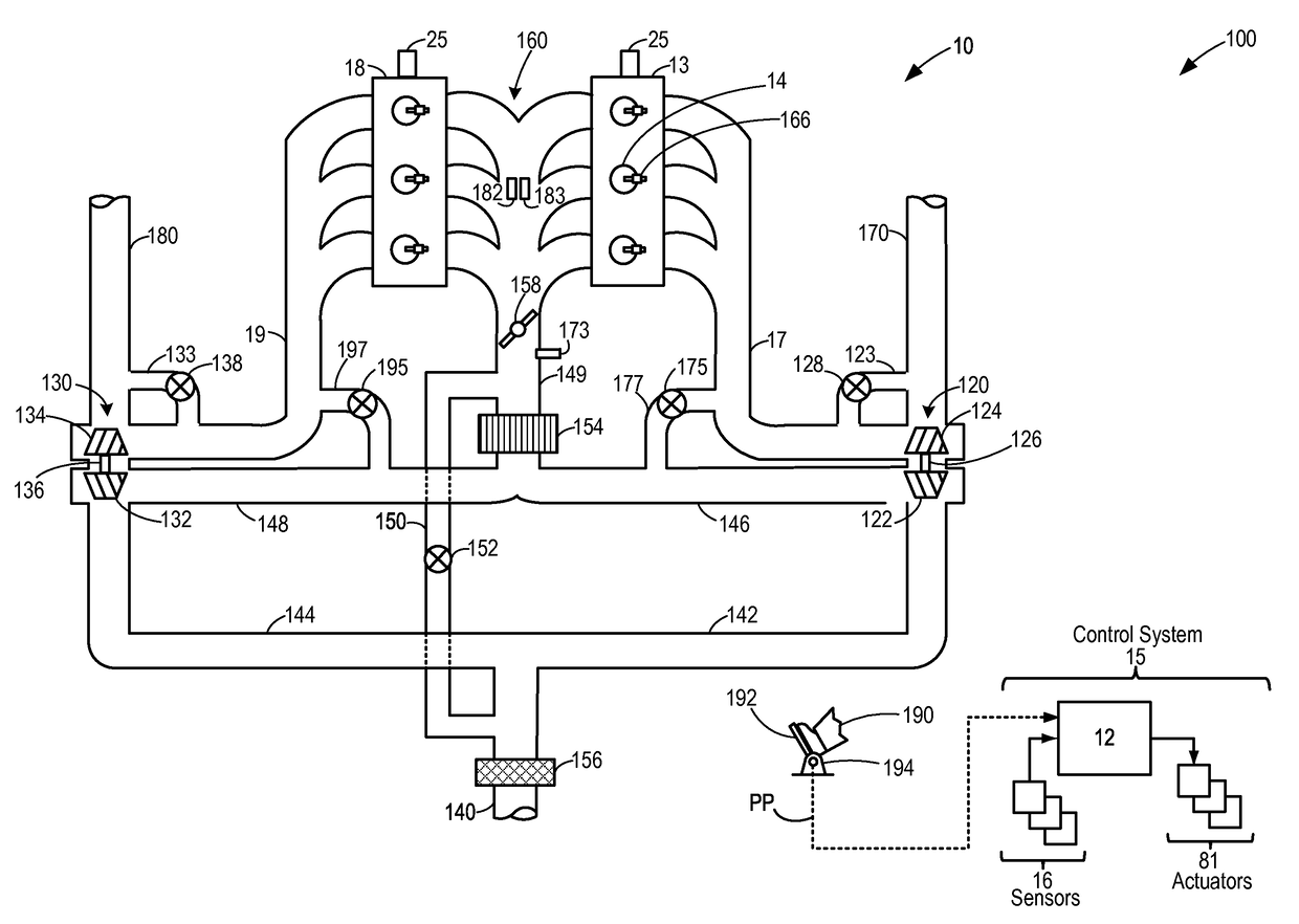
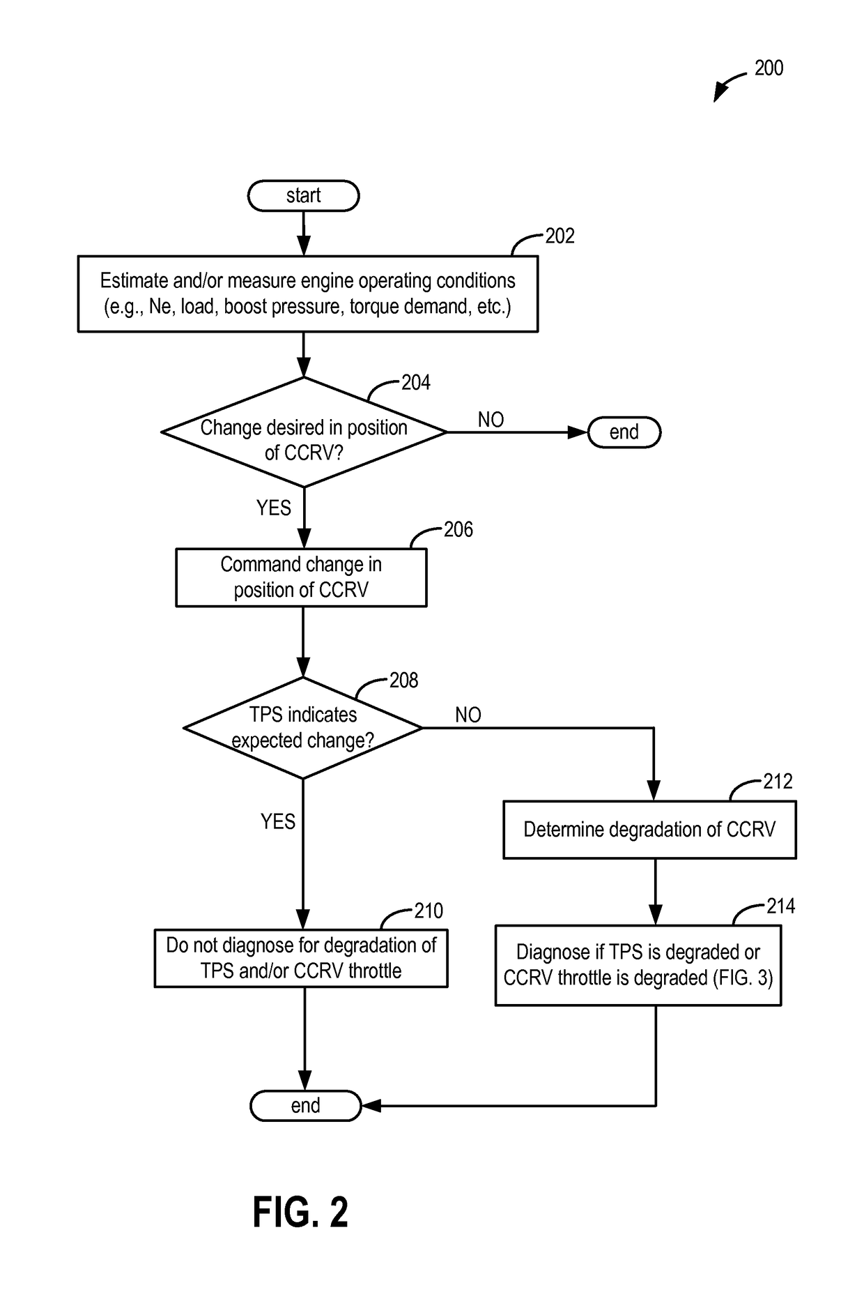
[0017]The following description relates to systems and methods for diagnosing degradation in a compressor recirculation valve (CRV) in a boosted engine system, such as the system of FIG. 1. A controller may be configured to perform a control routine, such as the routine of FIG. 2, to determine if the CRV is degraded. As such, the CRV may include a throttle whose position may be adjusted by the controller based on engine conditions. The CRV may also comprise a position sensor for confirming the change in position of the throttle of the CRV in response to a command by the controller. The controller may differentiate between degradation of the throttle of the CRV and degradation of the position sensor of the CRV by performing a control routine, such as the routine of FIG. 3, during engine operation. Degradation of the throttle of the CRV may be distinguished from degradation of the position sensor of the CRV based on each of a throttle inlet pressure, and a commanded position of the th...
PUM
| Property | Measurement | Unit |
|---|---|---|
| pressure | aaaaa | aaaaa |
| response time | aaaaa | aaaaa |
| inlet pressure | aaaaa | aaaaa |
Abstract
Description
Claims
Application Information