Instrument for measuring the distraction pressure between vertebral bodies

a technology of distraction pressure and instrument, which is applied in the field of instruments for measuring the distraction pressure between vertebrae, can solve the problems of inability to rule out the tilting of the vertebrae, inconvenient measurement of the distraction pressure, and inability to accurately measure the distraction pressure in this way, so as to improve the intervertebral disc prosthesis

Inactive Publication Date: 2011-10-20
COPF JR FRANZ
View PDF0 Cites 79 Cited by
  • Summary
  • Abstract
  • Description
  • Claims
  • Application Information

AI Technical Summary

Benefits of technology

[0011]The object of the invention consists in improving an instrument of the type mentioned in the introduction in such a manner that the treating physician is able to measure the distraction pressure under more realistic and better reproducible conditions. This may in turn, for example, enable the physician to configure better the intervertebral-disc prosthesis to be inserted.

Problems solved by technology

A disadvantageous aspect in this case, however, is that, owing to the shape of the instrument, an introduction of force during the distraction procedure occurs only on a small region of the hard osseous ring of the vertebral bodies.
Consequently a tilting of the vertebral bodies cannot be ruled out, even with parallel guidance of the adjusting arms of the instrument.
A distraction pressure measured in this way is therefore not very meaningful and is only helpful in limited manner in connection with the configuration of the intervertebral-disc prosthesis.

Method used


Image

  • Instrument for measuring the distraction pressure between vertebral bodies
  • Instrument for measuring the distraction pressure between vertebral bodies
  • Instrument for measuring the distraction pressure between vertebral bodies

Examples


Embodiment Construction

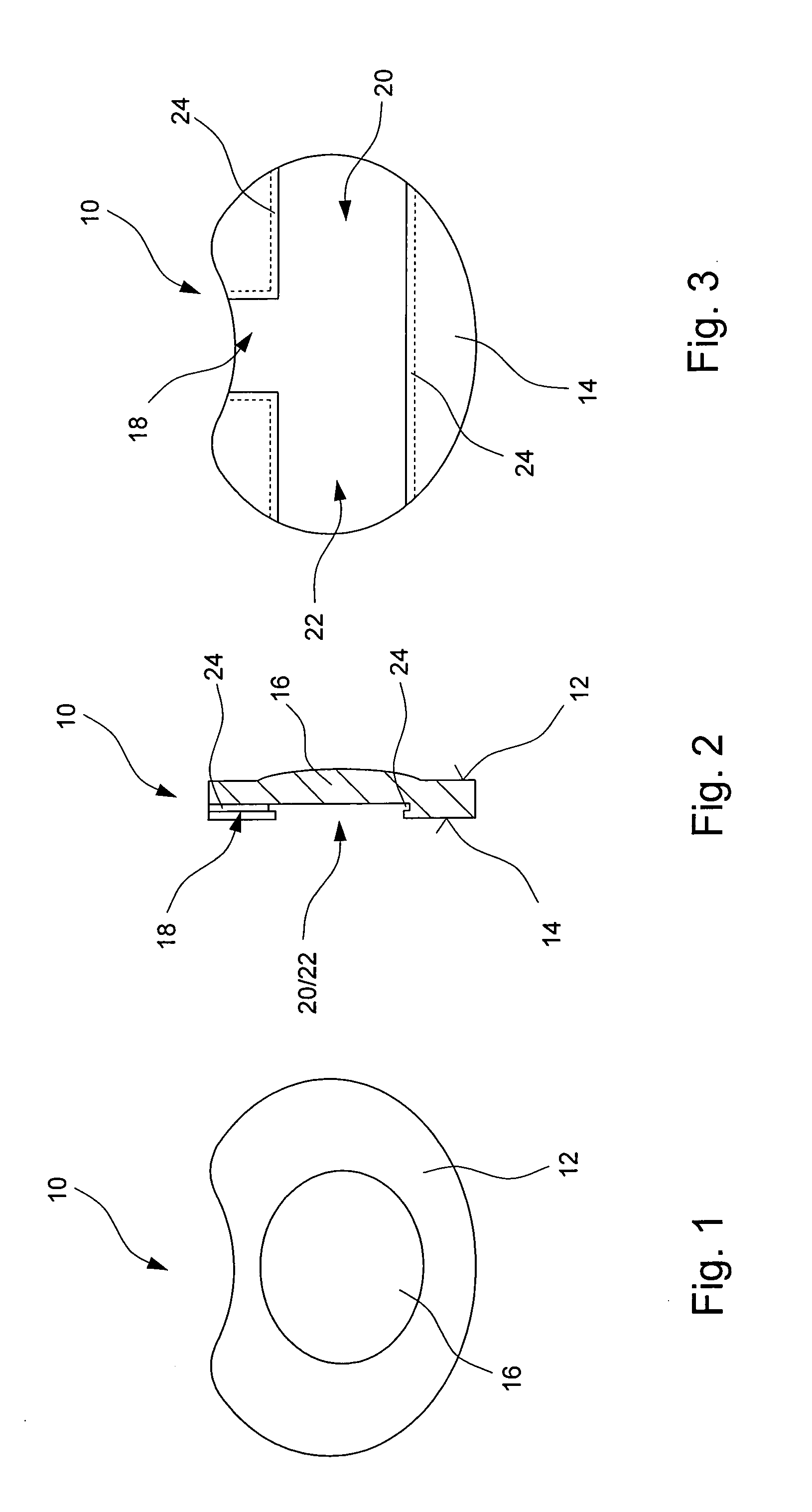
[0052]A prosthetic plate 10 represented in FIGS. 1 to 3 has been produced from a metallic material and exhibits a kidney-shaped outer contour which is evident in FIGS. 1 and 3. An upper side 12 of the prosthetic plate 10 serves for abutment against a vertebral body, which is not represented, and is provided with a vaulting 16 which is able to engage in a ring of harder bone material of the adjacent vertebral body. An underside 14 of the prosthetic plate 10 exhibits three shafts 18, 20, 22 which have been set up for receiving intermediate elements which are not represented. Shaft 18 serves for receiving a joint element which exhibits a concavely or convexly shaped spherical-cap-shaped region. The respective joint element forms with a corresponding joint element, which is attached to an opposite prosthetic plate 10, a ball joint with three rotational degrees of freedom of movement. Shafts 20 and 22 serve for receiving intermediate elements which are employed by way of swivel-angle lim...


PUM


Abstract

An instrument for measuring the distraction pressure between vertebral bodies comprises a control device (34, 36; 64, 66) for introducing a pressure force onto surfaces of opposing vertebral bodies and a measuring device (50; 84) associated with the control device (34, 36; 64, 66) for determining the pressure force applied onto the vertebral bodies. According to the invention, at least one end region of the control device (34, 36; 64, 66) carries a support body (10), which is designed for engaging in a concave dome that is surrounded by a bone ring of the vertebral bodies. The support body can be pivoted about at least one pivoting axis with respect to the control device and/or has a convex support surface, so that the support body when engaging into the dome can be pivoted in a sliding manner with respect to the vertebral body about at least one pivoting axis.

Description

BACKGROUND OF THE INVENTION[0001]1. Field of the Invention[0002]The invention relates to an instrument for measuring the distraction pressure between vertebral bodies, said instrument exhibiting an adjusting device for introducing a compressive force onto surfaces of opposed vertebral bodies and a measuring device, assigned to the adjusting device, for determining the compressive force exerted on the vertebral bodies.[0003]An instrument of such a type is known from DE 603 01 238 T2.[0004]2. Description of the State of the Art[0005]One possibility for treating damage to intervertebral discs consists in removing the damaged intervertebral disc and replacing it with an intervertebral-disc prosthesis. The intervertebral-disc prosthesis is inserted into an intervertebral-disc compartment in the vertebral column, said compartment being delimited by two adjacently arranged vertebral bodies.[0006]Intervertebral-disc prostheses are intended to guarantee as slight an impairment as possible of...

Claims


Application Information

Patent Timeline
Patent Type & Authority Applications(United States)
IPC IPC(8): A61B17/60A61B17/56
CPCA61B17/025A61B19/46A61B2019/461A61B2019/464A61F2250/0002A61F2/46A61F2/4684A61F2002/3067A61F2002/4666A61F2/442A61B2090/064A61B90/06A61B2090/061
Inventor COPF, JR., FRANZ
Owner COPF JR FRANZ
Why Eureka
Try Eureka