
Modular adjustable frame hand loom

Active Publication Date: 2011-10-27
SCHAUB RENE
View PDF42 Cites 61 Cited by
  • Summary
  • Abstract
  • Description
  • Claims
  • Application Information

AI Technical Summary

Benefits of technology

[0016]It is another object of the invention to provide a modular adjustable frame hand loom that is simple in construction and economical to manufacture.
[0021]It is an additional object of the invention to provide a hand loom that is simple and quick to assemble into a desired shape or configuration and disassemble for storage.
[0022]It is still an additional object of the invention to provide a hand loom as in the previous object in which end pegs or pins on each linear bar of the loom can be inserted into lined holes on matting tenon and mortise—type elements to lock associated or connected loom linear members or bars to prevent a situation of a loom after it has been assembled.
[0024]It is also another object of the invention to provide a kit that includes all component parts packaged together for retail sale to consumers in non-assembled form that allows the consumer to achieve the above mentioned objects.

Problems solved by technology

However, there are limitations associated with frame-knitting devices characterized by the prior art.
Typically, loops of yarn are attached or looped about the pegs and, depending on the spacing between the pegs it may be difficult to manipulate the loops.
By using such a construction, there is a limited ability to separate the bars and increase the distance between the pins on which the yarn is looped around.
However, there is no locking feature that maintains the connected sections connected to each other, and pulling one section of the frame relative to the other could separate the sections from each other.
The corner post may be used to adjust the trimmer in which the loom is adjusted for knitting articles of different sizes but cannot serve as pegs for looping yarn.
The frame is bulky and costly to produce and not intended to be assembled or disassembled by the user.
Failure to adequately tighten them may result in shifting of connected modules relative to one another and, therefore, modification of the desired frame geometry.
Therefore, by placing undesired stresses on the loom or loom sections the sections may inadvertently separate.
Additionally, because of the manner in which connected sections are disconnected from each other, requiring twisting of the elements relative to each other, this loom is less convenient and less easy to use since improper twisting may prevent quick or simple disassembly.

Method used


Image

  • Modular adjustable frame hand loom
  • Modular adjustable frame hand loom
  • Modular adjustable frame hand loom

Examples


Embodiment Construction

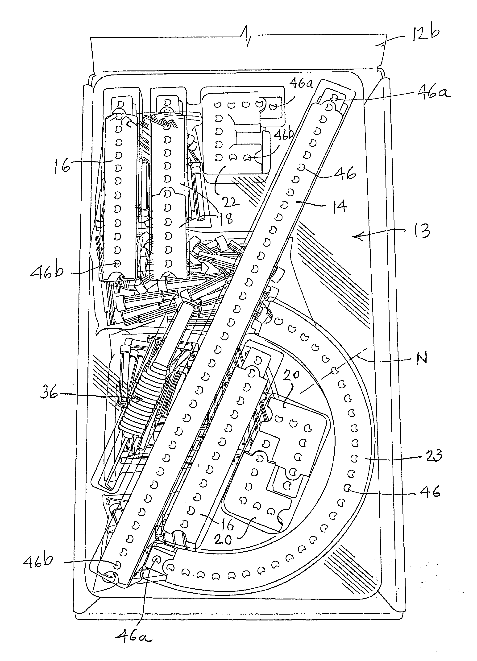
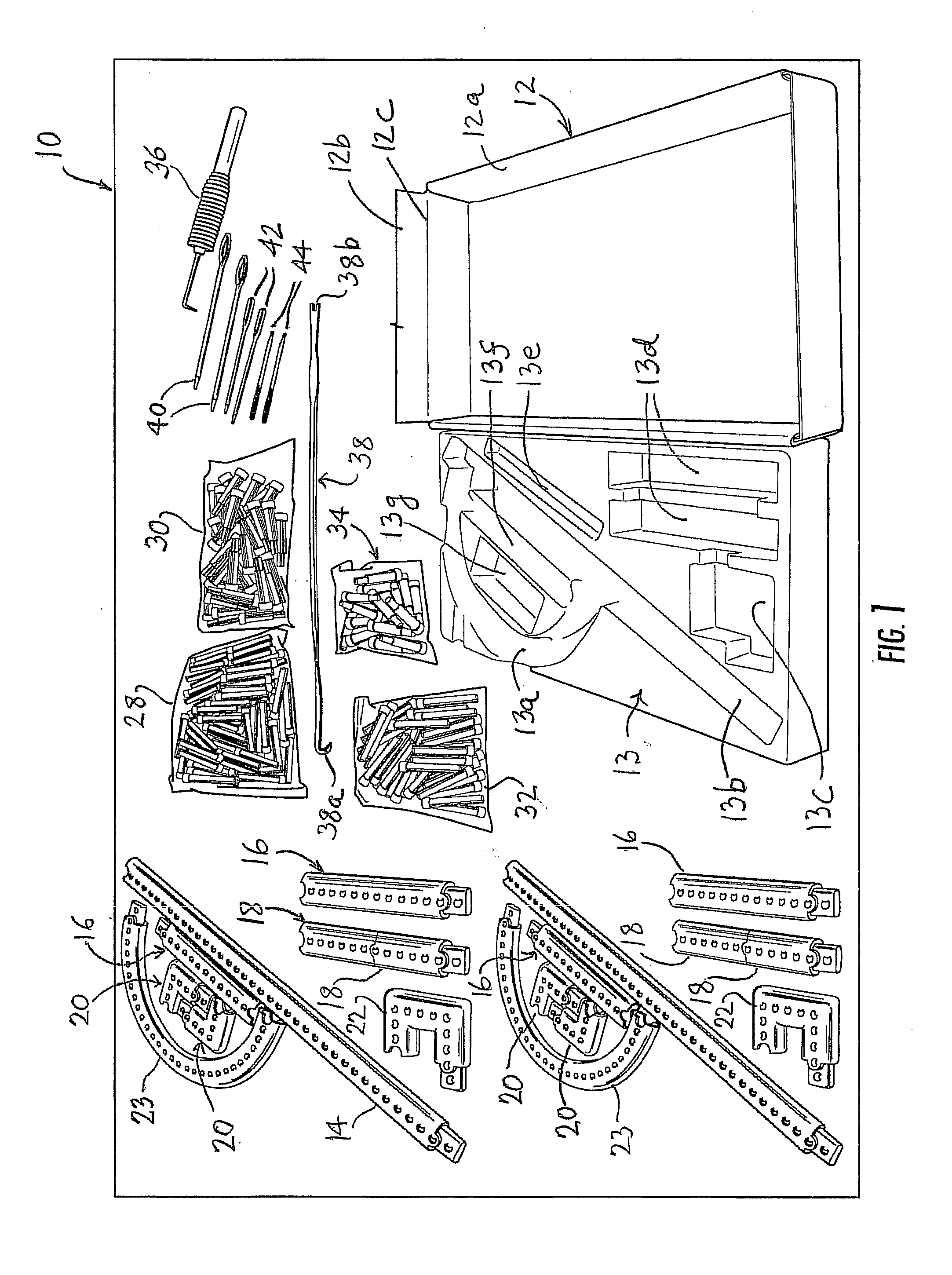
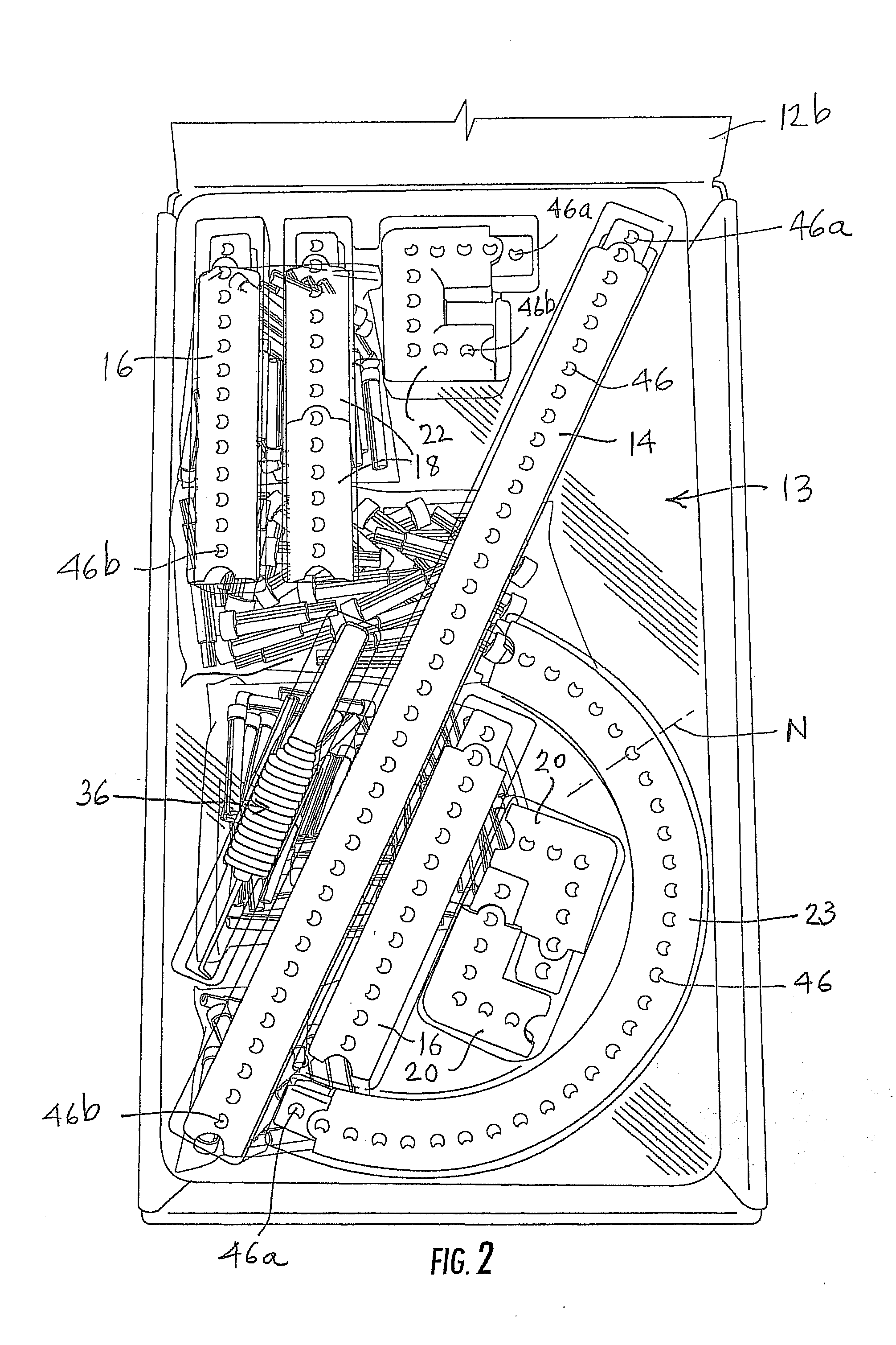
[0042]Referring now more specifically to the Figures, in which identical or similar parts are designated by the same reference numerals throughout, and first referring to FIG. 1, a kit for a modular adjustable frame hand loom is generally designated by the reference numeral 10.

[0043]The kit 10 includes a plurality of components or items that are packaged together for retail sale to consumers in a non-assembled form.

[0044]The kit 10 includes a box, carton or container 12 having a generally shallow rectangular receptacle 12a and a cover 12b, part of which has been removed for illustrative purposes, that is hinged about edge 12c for selectively exposing the receptacle 12a as shown or for closing the box and securing the components therein.

[0045]A tray or insert 13 is molded to generally conform to the interior space or compartment of the receptacle 12a so that it can be received therein with little clearance for the lateral movements. The insert or tray 13 includes recesses 13a-13g acc...


PUM


Abstract

An adjustable knitting and weaving hand loom includes differently shaped elongate sections. Tabs and channels connect the sections to form a closed frame by connecting adjoining sections in end-to-end abutment. The tabs and mating channels form sliding joints between adjoining sections. Each of the sections is provided with a series of substantially uniformly spaced holes or bores. End-most holes through the tabs and the channels are aligned when the axial tabs are fully slidably mated within associated axial channels. Pegs are dimensioned to be received both within aligned end-most holes at each slip joint and intermediate holes. The pegs are inserted into aligned end-most bores or holes function both to secure yarn during knitting and to lock the axial tabs from inadvertently separating from mating axial channels by movements along the direction of insertion.

Description

CROSS REFERENCE TO RELATED APPLICATION[0001]This application is related and claims priority of Provisional Patent Application Ser. No. 61 / 327,353 filed Apr. 23, 2010.BACKGROUND OF THE INVENTION[0002]1. Field of the Invention[0003]The present invention generally relates to frame looms and, more specifically, to a kit for a modular adjustable frame hand loom suitable for knitting and weaving yarns.[0004]2. Description of the Prior Art[0005]Knitting and weaving have long been popular hobbies and a large variety of items can be made on a loom in the form of a frame generally having a shape corresponding to the article to be made. A typical loom includes pegs that project from the frame around which the yarn is looped in various ways, such as running back and forth between opposite sides of the frame. However, there are limitations associated with frame-knitting devices characterized by the prior art. Typically, loops of yarn are attached or looped about the pegs and, depending on the sp...

Claims


Application Information

Patent Timeline
IPC IPC(8): D03D29/00B65D69/00D04B3/00
CPCD03D29/00D04B5/00D04B3/00
Inventor SCHAUB, RENE
Owner SCHAUB RENE
Learn More