Heavy duty tire
a heavy duty tire and tread technology, applied in the field of pneumatic tires, can solve the problems of low ground pressure and high possibility of being damaged by entrapped stones, and achieve the effects of preventing damage to the groove bottom and underlying tread reinforcing cord layer, reducing wet performance, and self-ejection of entrapped stones
Inactive Publication Date: 2011-10-27
SUMITOMO RUBBER IND LTD
View PDF8 Cites 20 Cited by
- Summary
- Abstract
- Description
- Claims
- Application Information
AI Technical Summary
Benefits of technology
[0011]It is therefore, an object of the present invention to provide a heavy duty tire, in which in order to prevent damage to the groove bottom and underlying
Problems solved by technology
In the tread crown region, the ground pressure is relatively high and the
Method used
View moreImage
Smart ImageViewing Examples
Examples
 PUM
 Abstract
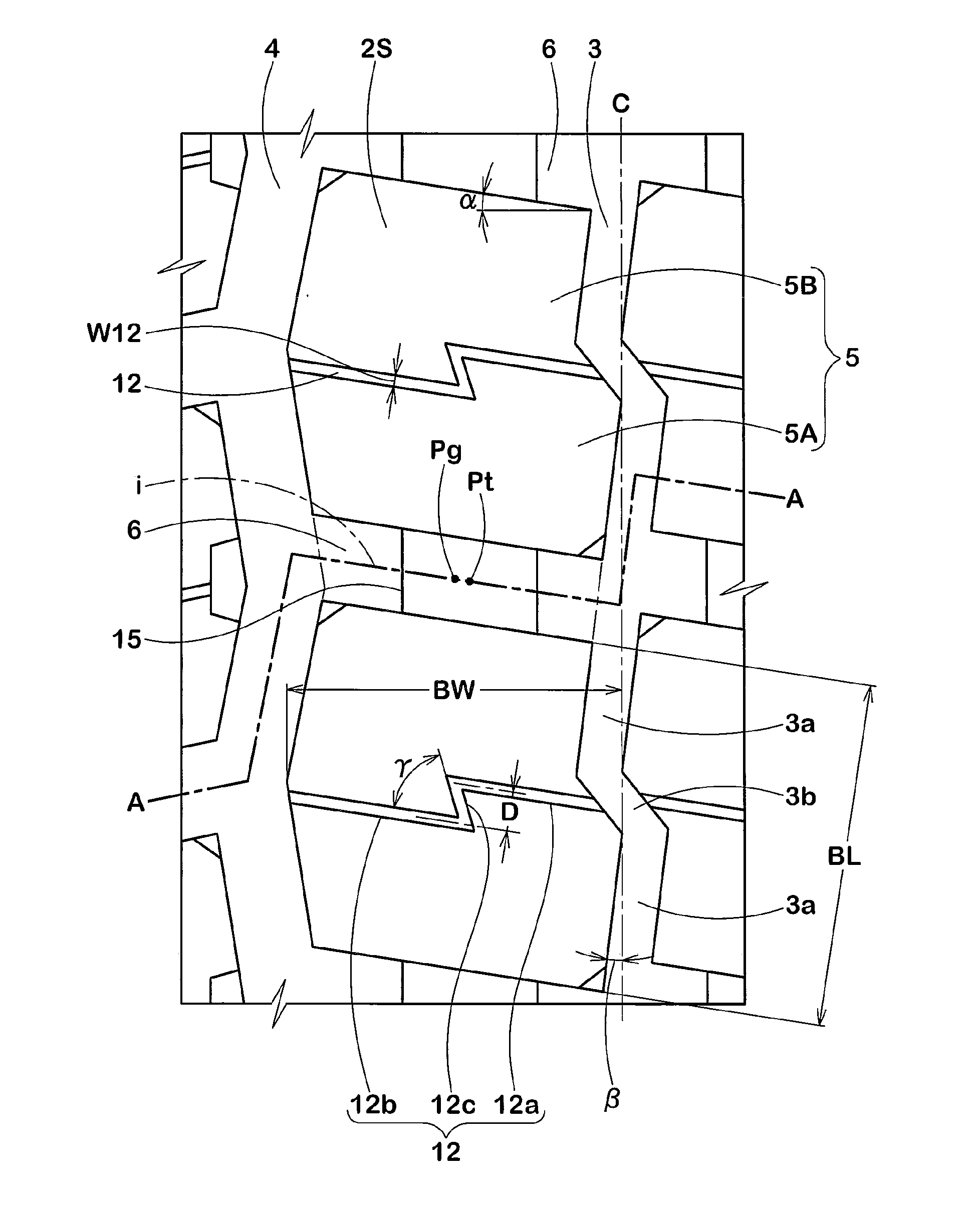
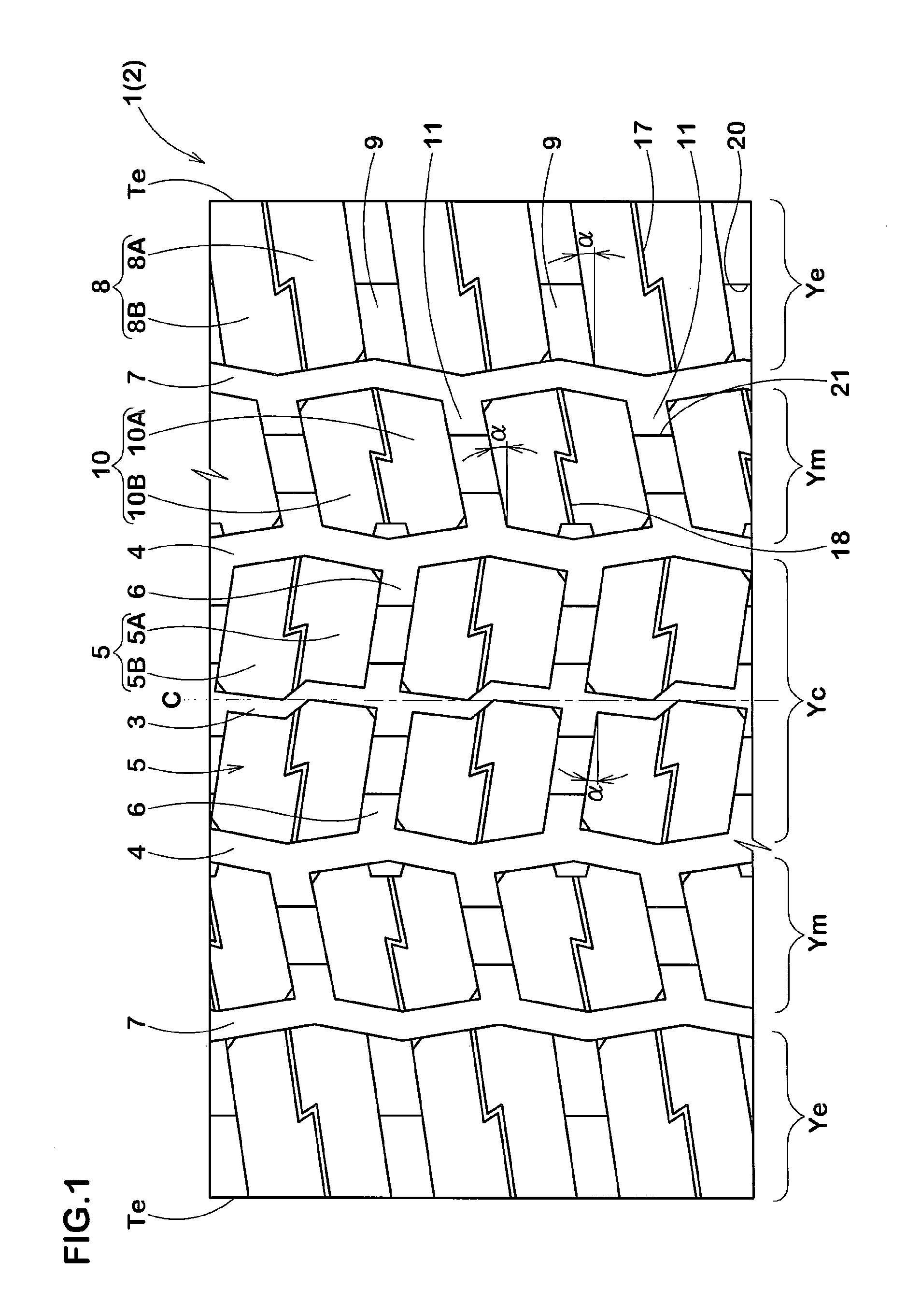
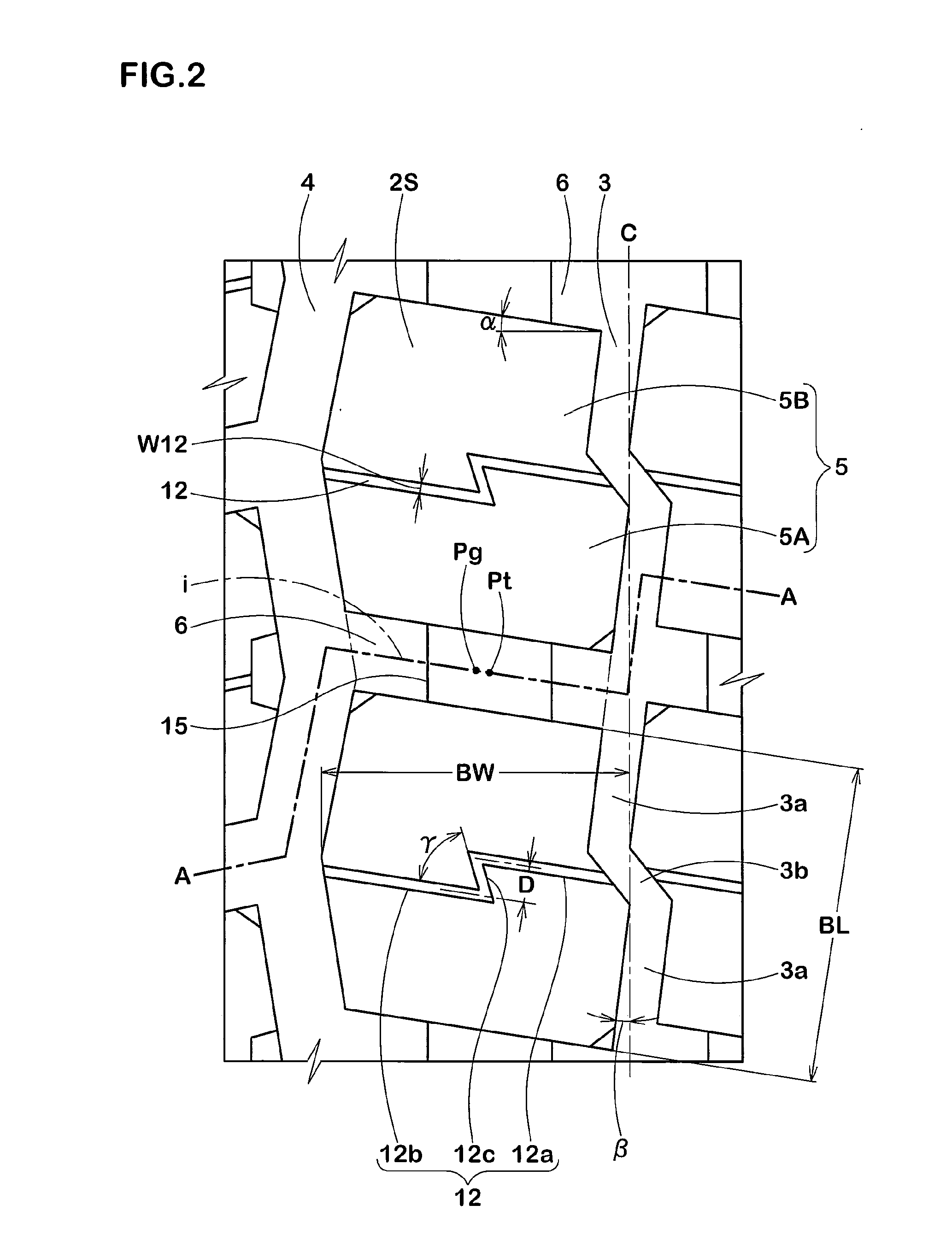
A heavy duty tire comprises a tread portion provided with a central circumferential groove, a crown circumferential groove on each side thereof and crown axial grooves extending therebetween so as to for crown blocks. The crown block is circumferentially subdivides into two block pieces by a crown narrow groove. The crown axial groove is provided in the groove bottom with a tie bar rising therefrom and connecting the circumferentially adjacent two crown blocks each other. The crown axial grooves are inclined at an angle α of from 10 to 30 degrees with respect to the tire axial direction. The central circumferential groove and an axially inner part of the crown axial groove which part is axially inside the tie bar, are shallower than the crown circumferential groove.
Description
BACKGROUND OF THE INVENTION[0001]The present invention relates to a pneumatic tire, more particularly to a heavy duty tire provided with a block pattern capable of improving self-ejection of stones entrapped in tread grooves.[0002]In the case of heavy duty tires for trucks and the like which are designed to be used on paved roads as well as unpaved roads for example gravel roads in construction fields, and provided in the tread portion with a block pattern in order to secure sufficient road grip on the unpaved roads, there is a tendency such that stones or small solid objects on the roads are entrapped in the tread grooves.[0003]If the entrapped stone remains in the tread groove and hits the groove bottom repeatedly during running, there is a possibility that the groove bottom as well as the underlying tread reinforcing cord layer are damaged and thereby the durability of the tread portion is deteriorated. Thus, there is a problem such that the retreadable rate of the used tires dec...
Claims
Login to View More Application Information
Patent Timeline
 IPC IPC(8): B60C11/13
CPCB60C11/0306B60C11/0309B60C2011/0372B60C11/1369B60C2200/06B60C11/12B60C11/11
Inventor SHIBANO, KEIZO
Owner SUMITOMO RUBBER IND LTD
Features
- R&D
- Intellectual Property
- Life Sciences
- Materials
- Tech Scout
- Unparalleled Data Quality
- Higher Quality Content
- 60% Fewer Hallucinations
Learn More Browse by: Latest US Patents, China's latest patents, Technical Efficacy Thesaurus, Application Domain, Technology Topic, Popular Technical Reports.
© 2025 PatSnap. All rights reserved.Legal|Privacy policy|Modern Slavery Act Transparency Statement|Sitemap|About US| Contact US: help@patsnap.com


