Adjustable heat exchanger

Inactive Publication Date: 2011-10-27
ALSTOM TECH LTD
View PDF9 Cites 27 Cited by
  • Summary
  • Abstract
  • Description
  • Claims
  • Application Information

AI Technical Summary

Benefits of technology

There is a chamber inlet 134 through chamber wall 132 proximate the outlet plenum 150. There is also a chamber outlet 136 through the chamber wall 132 proximate the inlet plenum 110. Transfer fluid is provided from a transfer fluid source 170 through the chamber inlet 134, through the interstitial spaces 139 and out the chamber outlet 136 in a direction substantially opposite that of the working fluid. There is also a plurality of bypass outlets 183 through the chamber wall 132 each proximate the inlet plenum 150. A plurality of bypasses 180 each fluidically connect the transfer fluid source 170 to one of the bypass outlets 183. This allows the transfer fluid to bypass a portion of the central chamber 130 and cool structures proximate the inlet plenum 110 to reduce heat failures.
The present invention may also be embodied as a method of reducing heat failure in a heat exc

Problems solved by technology

If the input flows of the fluids are improperly varied, there is the risk of providing less fluid than is required for cooling portions of the heat exchanger, thereby “starving” the heat exchanger of needed cooling leading to overheating and premature failure of the heat exchanger.
This eventually causes failure of the metal and also failure of the heat exchanger.
Howev

Method used


Image

  • Adjustable heat exchanger
  • Adjustable heat exchanger

Examples


Embodiment Construction

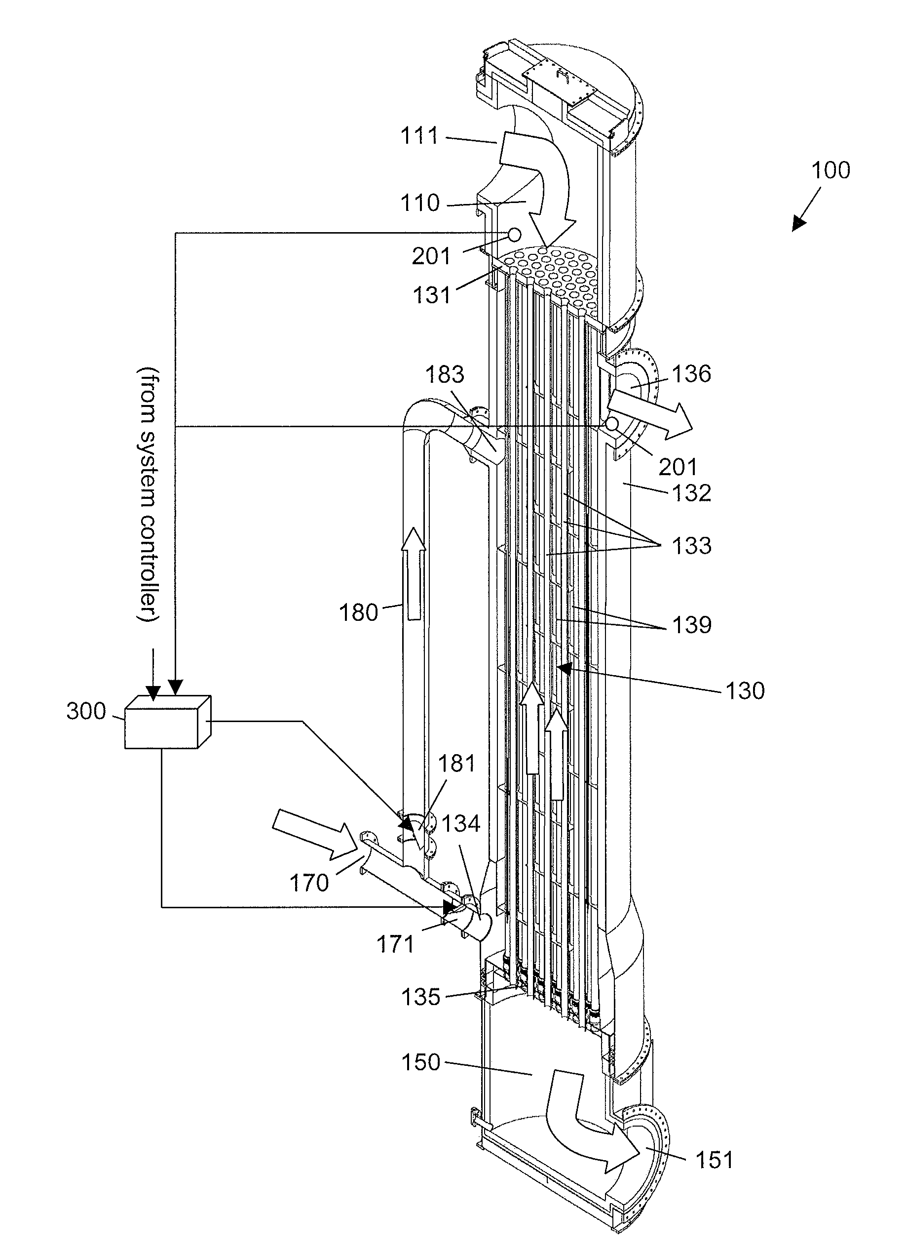
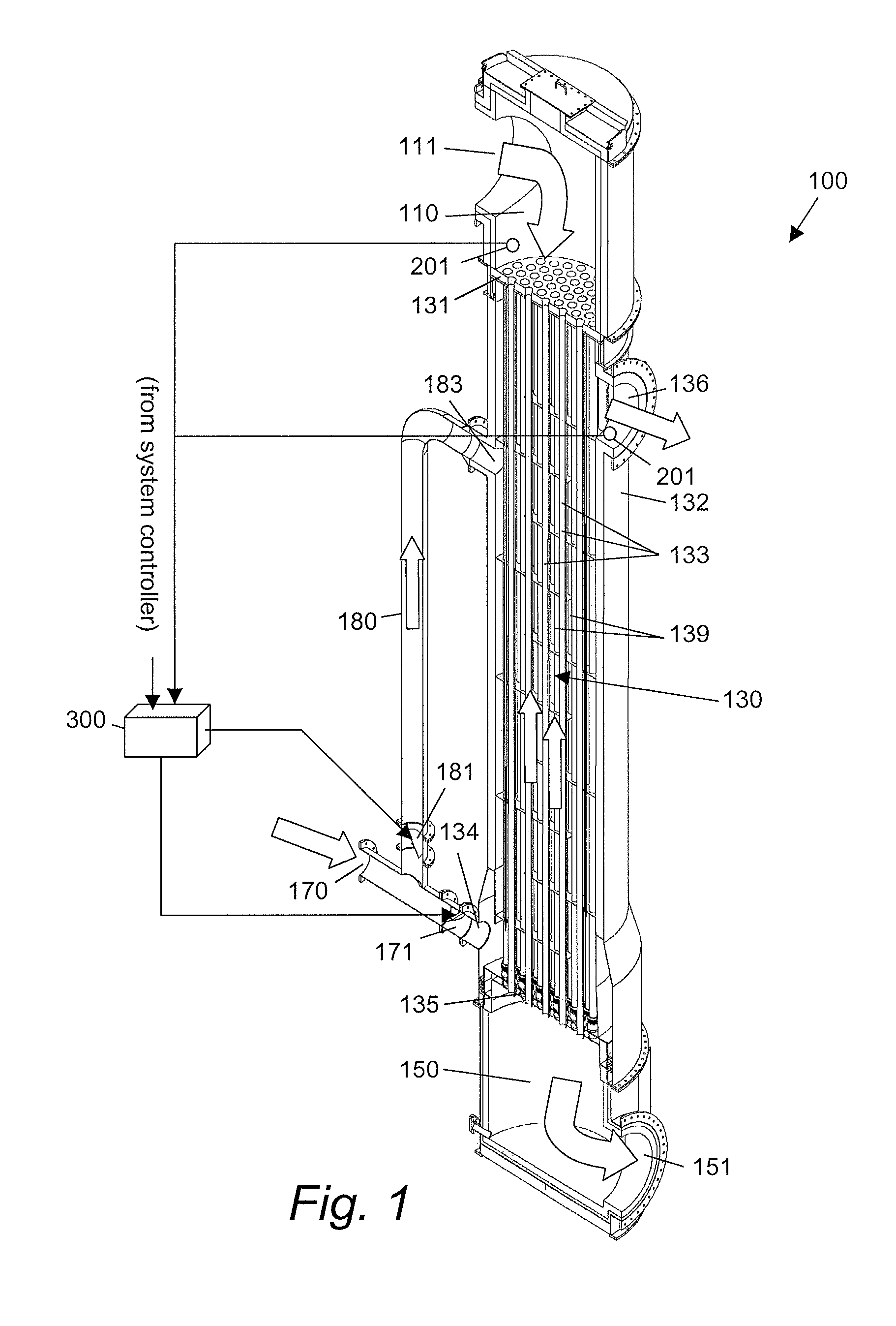
As described above, conventional heat exchangers adjust transfer fluid temperature by changing flow rate of either the first or transfer fluid. This can reduce efficiency. For example, if the hot working fluid is a flue gas stream from a furnace and the cold transfer fluid is an air stream intended to be routed into the combustion chamber of the furnace, adjusting the temperature by controlling the flow of flue gas or of combustion air causes a less than optimum performance of the furnace. There is a defined amount of flue gas produced, and a defined optimum amount of combustion air used.

The means to minimize overheating of the heat exchanger is by employing an interstage bypass of the heated transfer section of the heat exchanger. A portion of the cool transfer fluid inlet stream is allowed to bypass a section of the heat exchanger, and then it is re-introduced into an upper section of the heat exchanger. By this means there is full flow of the transfer fluid over the hottest end o...


PUM


Abstract

Disclosed herein is a novel, adjustable heat exchanger 100 for reliably exchanging heat from a hot working fluid to a transfer fluid. The working fluid passes through an inlet plenum 110, at least one conduit 133 that may be a tube or a plurality of tubes, and out of an outlet plenum 150. A chamber wall 132 encloses the conduits 133 creating a central chamber 130 having interstitial spaces 139 around the conduits 133. A transfer fluid passes through the interstitial spaces in a direction substantially opposite the working fluid, absorbing heat from the conduits 133. A bypass 180 fluidically connects the transfer fluid source 170 to central chamber 130 proximate the inlet plenum 110. Cool transfer fluid bypasses a portion of the central chamber and is provided directly to the central chamber 130 proximate the inlet plenum 110 to cool structures there and reduce heat failures, while providing a constant flow of transfer fluid out of the heat exchanger 100.

Description

BACKGROUND1. Field of the InventionThis disclosure relates to a device that exchanges heat from one fluid to another, and more specifically to a to a device that exchanges heat from one fluid to another that is more reliable and effective compared with the prior art.2. Discussion of Related ArtTypically heat exchangers are fixed surface devices that passively process multiple streams of gases / liquids / solids. Heat is transferred from the hot working fluid stream to the cooler transfer fluid stream by means of conduction, convection or radiation. Since they are passive devices, when the streams change temperature, flow or composition, then the performance of the heat exchanger changes as well.In many processes it is desirable to have some level of control of the heat exchanger performance. This can sometimes be accomplished by varying the input flow of either fluid, by introducing recirculation flows or dilution by another fluid to one fluid stream or the other. If the input flows of ...

Claims


Application Information

Patent Timeline
IPC IPC(8): G05D23/00F28F9/00
CPCF23L15/04F28D7/16F28F2009/226F28F2250/06F28F27/02Y02E20/34
Inventor ANGEL, JOHN H.HOMOKI, GREGORY G.
Owner ALSTOM TECH LTD
Why Eureka
Try Eureka