
Special container for mobile extrusion equipment

a technology for mobile extrusion equipment and containers, applied in the field of containers, can solve the problems of high transportation costs, waste, extra connection work, etc., and achieve the effects of reducing some production and usage procedures, saving costs and processing time, and reducing unnecessary was

Inactive Publication Date: 2011-10-27
CHEN YUANWEN
View PDF7 Cites 12 Cited by
  • Summary
  • Abstract
  • Description
  • Claims
  • Application Information

AI Technical Summary

Benefits of technology

"The present invention provides a special container for mobile extrusion equipment that can reduce production and usage procedures, save costs and processing time, reduce unnecessary waste, improve production efficiency, and make it easier to produce and process extrusion products in a poor environment. The container is designed to be easily moved and can be set up quickly. It includes a base, side plates, extrusion equipment, a water pump, a lifting windlass, a track, and a canvas covering the extrusion equipment. The container can be expanded and has a reservoir for storing water. It also has a track for moving the extrusion equipment and a variety of additional functions such as a workstation, lounge, washroom, and medical kit. The container solves packaging and transportation problems and reduces production and usage procedures, saving costs and processing times."

Problems solved by technology

As the products are hollow inside, much space in the transportation vehicles is wasted, resulting in high transportation costs.
However, as customers usually have different requirements for the length of products, unneeded parts are cut off, which results in huge waste.
Also because longer products cannot be produced, there is extra connection work as well as an increase in additional installation expenditures.

Method used


Image

  • Special container for mobile extrusion equipment
  • Special container for mobile extrusion equipment
  • Special container for mobile extrusion equipment

Examples


Embodiment Construction

[0022]The following is a further description of the present invention with reference to the figures and the embodiments, but without a limitation to the present invention.

[0023]A preferred embodiment is as below:

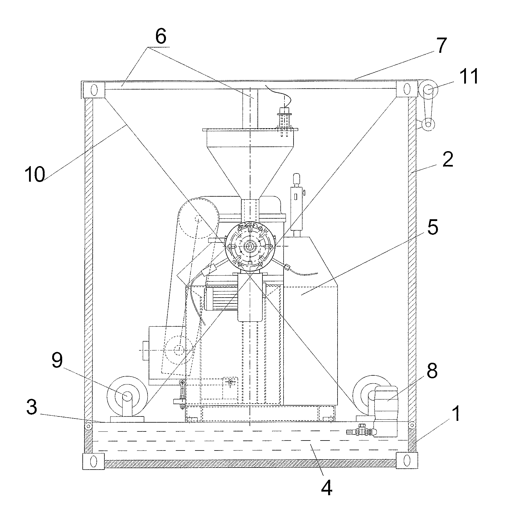
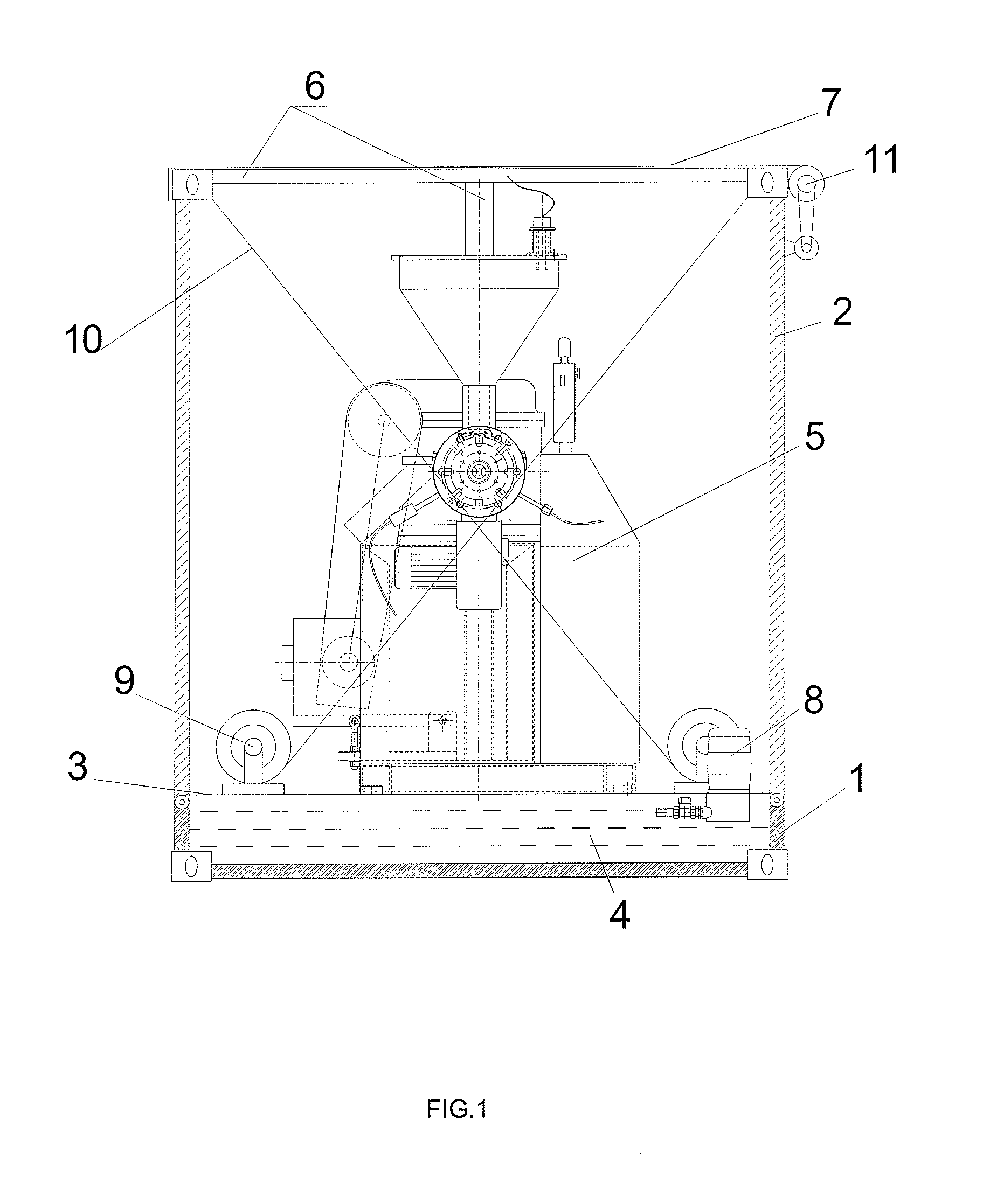
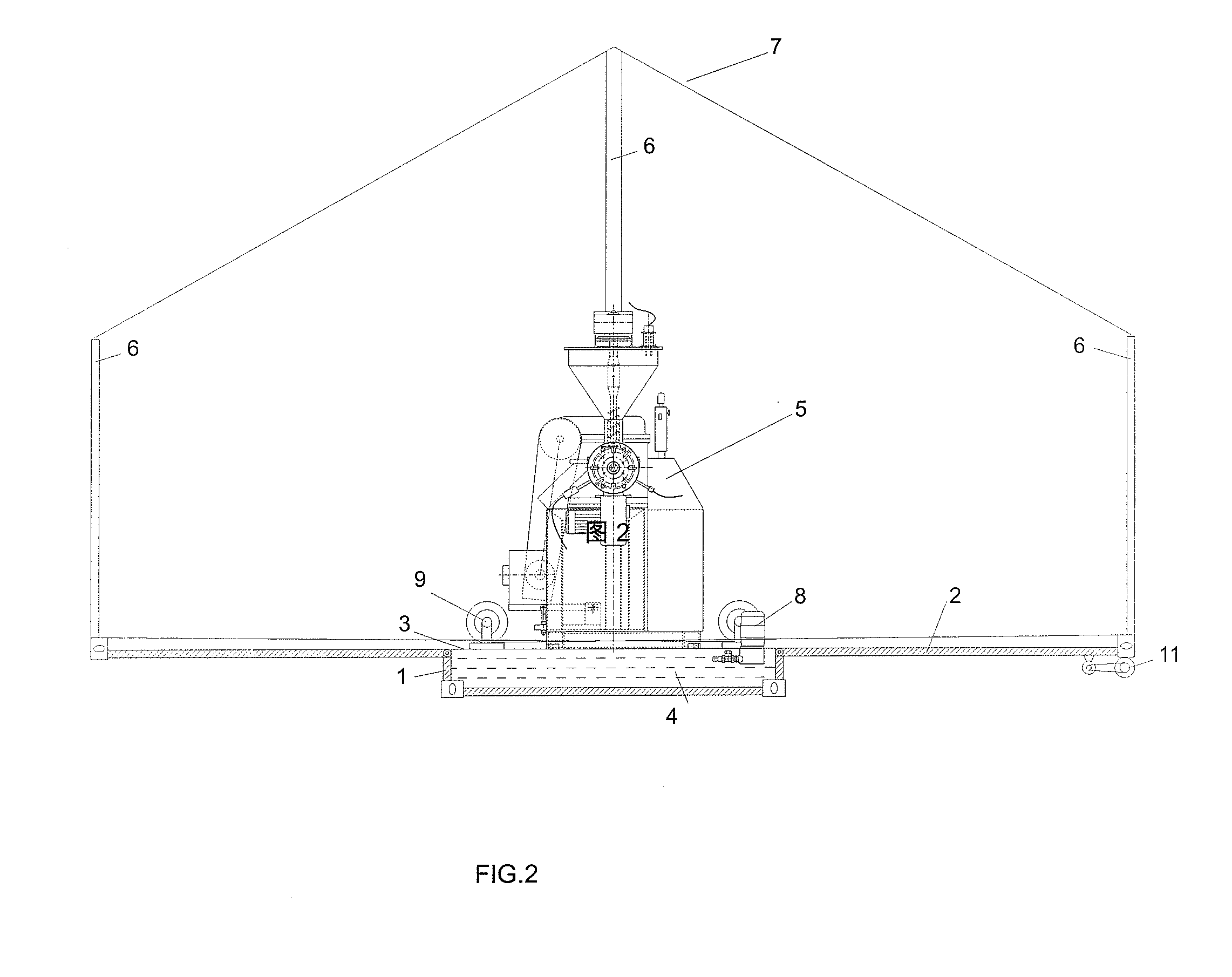
[0024]A special container for mobile extrusion equipment, comprising a case 1, the side plates 2 are articulated around the base 1, a floor 3 is set above the said base 1, a reservoir 4 is set under the floor 3, the extrusion equipment 5 is set above the floor 3, a simple holder 6 is set on the said side plates 2, and a piece of canvas 7 covers the simple holder 6.

[0025]A water pump 8 is set on the floor 3 above the reservoir 4.

[0026]A lifting windlass 9 is set above the floor 3, and the said lifting windlass 9 is connected to the top of the said side plates 2 through a steel wire rope 10.

[0027]The canvas 7 is connected to the canvas crimping machine 11 on the side plates 2.

[0028]The track 12 is set above the floor 3, and said extrusion equipment 5 is set above the said trac...


PUM

PropertyMeasurementUnit
volumeaaaaaaaaaa
lengthsaaaaaaaaaa
lengthaaaaaaaaaa

Abstract

A special container for mobile-type ex-truding equipment includes a base (1), side boars (2) are hinged on the periphery of the base (1), a base floor (3) is fixed on the base (1), a reservoir (4) is fixed under the base (1), an extruding equipment (5) is fixed on the base floor (3), a simple bracket (6) is fixed on the side boards (2), the simple bracket (6) is covered with a sailcloth (7), This special container reduces the production and uses of intermediate links, reduces costs and processing time, reduces unnecessary waste and increases production efficiency, and is easy to in harsh environments extrusion-type products processing.

Description

BACKGROUND OF THE INVENTION[0001]1. Technical Field[0002]The present invention relates to a container, and more especially, to a special container for mobile extrusion equipment.[0003]2. Description of Related Art[0004]The products made by extrusion methods in the prior art are all produced in a fixed workshop. Most of the products are hollow inside, and are transported to customers or sites for use by various transportation vehicles (including trucks, ships and trains) after being finished in a workshop. As the products are hollow inside, much space in the transportation vehicles is wasted, resulting in high transportation costs. Moreover, due to the limitations of transport vehicles, products are produced in fixed lengths in factories for better loading, unloading and stacking. However, as customers usually have different requirements for the length of products, unneeded parts are cut off, which results in huge waste. Also because longer products cannot be produced, there is extra...

Claims


Application Information

Patent Timeline
Patent Type & Authority Applications(United States)
IPC IPC(8): B65D85/00
CPCB29C47/0023B29C47/08B29C47/0864B29C2947/9298B29C47/0872B29C47/90B29C47/0867B29C48/09B29C48/25B29C48/265B29C48/2665B29C48/269B29C48/90B29C48/905B29C2948/9298
Inventor CHEN, YUANWEN
Owner CHEN YUANWEN
Learn More