High power density switched reluctance machines with hybrid excitation

a technology of switched reluctance machines and hybrid excitation, which is applied in the direction of dynamo-electric converter control, motor/generator/converter stopper, synchronous motors, etc., can solve the problems of loss of the best operational features of srms, difficulty in manually wrapping windings on the poles, and increased flux leakage. to achieve the effect of enhancing the torque production of srm

Active Publication Date: 2011-10-27
REGAL BELOIT AMERICA
View PDF12 Cites 35 Cited by
  • Summary
  • Abstract
  • Description
  • Claims
  • Application Information

AI Technical Summary

Benefits of technology

[0031]Still further, an object of the invention is to have no leakage paths in a machine's back iron. Alternating current (ac) operation of the excitation windings is possible without PM flux opposing stator excitation pole flux and with only reluctance torque contributing to the dominant torque. The PM flux aids the stator excitation poles flux and at no time do they oppose each other.
[0037]The above-mentioned and other objects of the invention may be achieved, in full or part, by a method of operating a switched reluctance machine (SRM), the SRM having: (a) a rotor, (b) a stator having multiple poles, each of which has an inductive winding disposed thereon and fewer than all of the poles have a permanent magnet disposed thereon; and (c) a stator back that electromagnetically interconnects the poles. The method including: (1) inducing flux within the SRM by passing current through one or more of the inductive windings that is not disposed on a stator pole having a permanent magnet thereon; and (2) inducing flux within the SRM by passing current through one or more of the inductive windings disposed on a stator pole having a permanent magnet thereon so as to correct a power factor applied to the SRM or enhance torque production of the SRM.

Problems solved by technology

Placing PMs in a stator back iron creates operation that is not that of a switched reluctance machine drive system, but is that of a PM brushless direct current (dc) motor drive system, which causes the loss of the best operational features of SRMs while embracing only the standard features of a PM brushless dc motor (PMBDC) drive system.
Flux produced by the stator current excitation passes through adjacent stator poles, resulting in greater flux leakage.
The wide face of each stator pole, as illustrated in FIGS. 2 and 3, increases the difficulty of manually wrapping windings on the poles and automated winding insertion is expensive.
A challenge facing machine 500 is that the starting torque at an unaligned position of the rotor and stator poles is not very high.

Method used


Image

  • High power density switched reluctance machines with hybrid excitation
  • High power density switched reluctance machines with hybrid excitation
  • High power density switched reluctance machines with hybrid excitation

Examples


Embodiment Construction

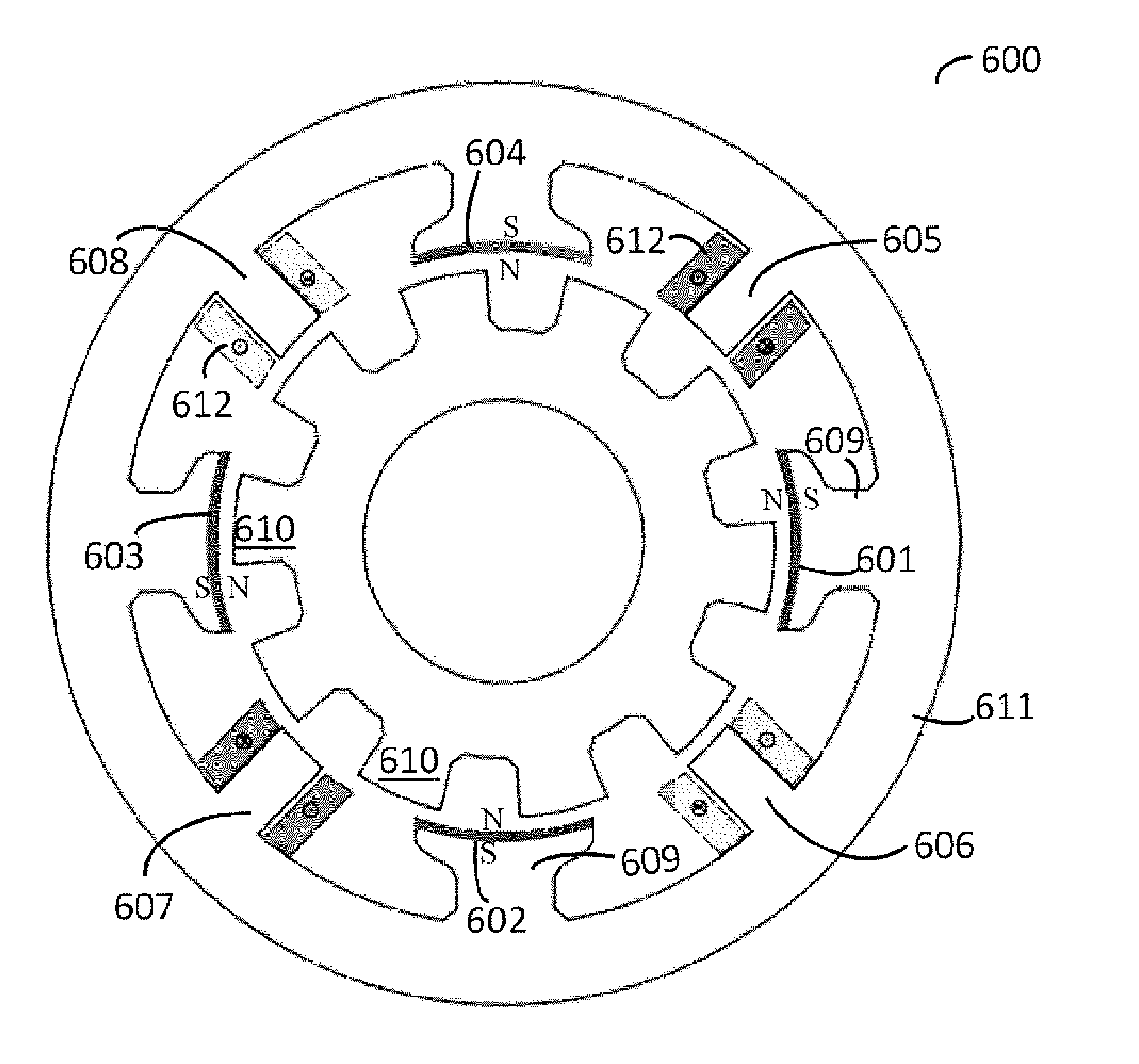
[0056]FIG. 6 illustrates a machine 600 having permanent magnets (PMs) disposed on the faces of a stator's common poles. A PM 601, 602, 603, 604 is mounted on the face of each of common poles 609 with south poles forming the base and north poles directly facing rotor poles 610 and the air gaps in between. Excitation poles 605-608 all generate and conduct flux away from the air gap existing between the rotor and stator poles, into the excitation poles, and then into stator back iron 611. The polarities of current excitations (dot indicating current coming out and star indicating current going in the conductors) are shown in windings 612 around excitation stator poles 605-608. The PM flux goes to the adjacent excitation poles of both phases under normal conditions, when excitation poles 605-608 are not energized. A dominant portion of the PM flux passes through the excited excitation pole.

[0057]For example, exciting phase-A winding on excitation stator poles 605, 607 will draw the flux...


PUM


Abstract

A switched reluctance machine having salient stator and rotor poles. Alternating ones of the stator poles having windings and the others having permanent magnets attached on their pole faces. The alternate stator pole windings are provided with polarities that are suitable for unidirectional and bidirectional current operation of the switched reluctance machine. The alternate poles with permanent magnets in the switched reluctance machines can have also concentric windings placed on them and excited with currents to further augment the flux linkages in the stator poles. The windings on the poles with permanent magnets can be excited from the same source as the windings on the poles without permanent magnets to enhance power output or provide power factor correction.

Description

[0001]This application claims the priority benefit of U.S. provisional application 61 / 327,829 filed on Apr. 26, 2010, the entire content of which is incorporated here by reference.FIELD OF THE INVENTION[0002]The invention relates to increasing the torque and power output of a switched reluctance machine (SRM), having windings on alternate stator poles, by augmenting the stator flux with permanent magnets placed directly on the stator poles that have no stator windings. The invention also relates to an SRM having windings on all of its stator poles and permanent magnets only on the alternate stator poles, so as to increase the stator flux, torque, and power output. The invention further relates to unidirectional and bidirectional current operation of an SRM with permanent magnets on alternate stator poles having no windings on them. Still further, the invention relates to unidirectional and bidirectional current operations of an SRM having windings on all poles but permanent magnets ...

Claims


Application Information

Patent Timeline
Patent Type & Authority Applications(United States)
IPC IPC(8): H02P25/08H02K19/06
CPCH02P25/08H02K21/44Y02P80/10
Inventor RAMU, KRISHNAN
Owner REGAL BELOIT AMERICA
Why Eureka
Try Eureka