Frequency setting circuit and method for an integrated circuit

a technology of frequency setting circuit and integrated circuit, which is applied in the direction of oscillator generator, pulse automatic control, instruments, etc., can solve the problem that the pins of the integrated circuit will not be enough to suppor

Active Publication Date: 2011-10-27
RICHTEK TECH
View PDF3 Cites 0 Cited by
  • Summary
  • Abstract
  • Description
  • Claims
  • Application Information

AI Technical Summary

Benefits of technology

[0008]The frequency setting circuit according to the present invention is constructed from digital circuits and thus is capable of storing the frequency setting signal. After setting the frequency, the frequency setting circuit can maintain the frequency of the clock according to the frequency setting signal it stores, without keeping detecting the voltage at the pin. In other words, after the frequency setting, the pin can be used to implement other functions.

Problems solved by technology

With integrated functions increasing, the pins of an IC will be not enough to support, especially in low pin count ICs.

Method used


Image

  • Frequency setting circuit and method for an integrated circuit
  • Frequency setting circuit and method for an integrated circuit
  • Frequency setting circuit and method for an integrated circuit

Examples


first embodiment

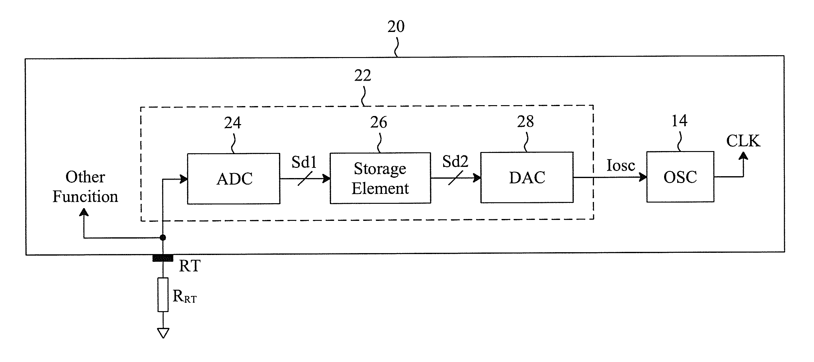
[0019]FIG. 5 is a first embodiment for the ADC 24, the storage element 26 and the DAC 28 of FIG. 3. In the ADC 24, a current source 30 provides a constant current IRT to the pin RT, so as to generate a constant voltage

VRT=IRT×RRT,  [Eq-5]

and a comparator 32 compares the voltage VRT with a threshold Vth to generate the first digital signal Sd1. The storage element 26 has a counter 34 to adjust the second digital signal Sd2 by counting the first digital signal Sd1, and to store the second digital signal Sd2 in response to a sampling signal SH. The soft-start end signal PORD of FIG. 4 may be used as the sampling signal SH and thus, when the soft-start end signal PORD turns to high from low at time t2, the counter 34 will store the second digital signal Sd2. The DAC 28 generates the frequency setting signal Iosc and the threshold Vth according to the second digital signal Sd2. The counter 34 adjusts the second digital signal Sd2 according to the first digital signal Sd1, so as to make t...

second embodiment

[0020]FIG. 7 is a second embodiment for the ADC 24, the storage element 26 and the DAC 28 of FIG. 3, in which the ADC 24 has the comparator 32, the storage element 26 has the counter 34, and the DAC 28 generates a current IRT and the frequency setting signal Iosc according to the second digital signal Sd2. The current IRT flows to the resistor RRT through the pin RT, so as to generate the voltage VRT as shown in the equation Eq-5. In this embodiment, the current IRT varies with the second digital signal Sd2, so the voltage VRT also varies with the second digital signal Sd2. In the ADC 24, the comparator 32 compares the voltage VRT with a reference voltage Vref to generate the first digital signal Sd1. The counter 34 of the storage element 26 adjusts the second digital signal Sd2 according to the first digital signal Sd1, so as to make the voltage VRT vary toward the reference voltage Vref. Assuming that the frequency setting signal Iosc is equal to the current IRT, and the voltage V...


PUM


Abstract

A frequency setting circuit and method for an integrated circuit detect the voltage at a pin of the integrated circuit during a frequency setting period, and determine a frequency setting signal according to the detected voltage to set the frequency of a clock provided by an oscillator in the integrated circuit. After setting the frequency, the frequency setting circuit and method store the frequency setting signal and stop detecting the voltage at the pin. Thus the pin can be used for other functions.

Description

FIELD OF THE INVENTION[0001]The present invention is related generally to a circuit and method for frequency setting of integrated circuits and, more particularly, to a frequency setting circuit and method implemented by digital circuits.BACKGROUND OF THE INVENTION[0002]For integrated circuits (ICs), traditional design needs external frequency setting with dedicated pin to continuous setting. Therefore, the pin count is more and more critical, especially in low pin count ICs. For example, referring to FIG. 1, an IC 10 has a pin RT to be connected with an external resistor RRT, a frequency setting circuit 12 to determine a frequency setting signal Iosc depending on the resistance of the resistor RRT, and an oscillator 14, according to the frequency setting signal Iosc, to generate a clock CLK with the frequencyFclk=k1×Iosc,  [Eq-1]where k1 is a proportionality coefficient. The frequency setting circuit 12 includes an operational amplifier 16, a transistor M1 and a current mirror 18 e...

Claims


Application Information

Patent Timeline
Patent Type & Authority Applications(United States)
IPC IPC(8): H03L7/00
CPCH03L7/099
Inventor LU, SHAO-HUNGCHEN, ISAAC Y.
Owner RICHTEK TECH
Why Eureka
Try Eureka