Control device and method for controlling the laser beam deflection

a control device and laser beam technology, applied in the direction of optical elements, instruments, manufacturing tools, etc., can solve the problems of inertia and acceleration/deceleration, possible errors, and scanner needs a very fast discontinuous mechanical movement, etc., to achieve high resolution, high complexity, and high accuracy

Active Publication Date: 2021-05-25
SIEMENS AG
View PDF15 Cites 0 Cited by
  • Summary
  • Abstract
  • Description
  • Claims
  • Application Information

AI Technical Summary

Benefits of technology

[0034]Preferably the Lissajous curve is closed. Thus closed curves are only produced when the ratio of the frequencies is rational, otherwise the vibration practically never ends. In a preferred embodiment the frequencies and the phase difference can be selected such that the Lissajous curve is a grid with sufficient accuracy. Preferably the first and also the second frequency and the phase difference are embodied such that the Lissajous curve is able to be formed as an internal low-distortion ideal grid and external outer grid. Such a grid is visible when the first and also the second frequency lies in the range of 10 kHz for example, and the phase difference lies in the range 100 Hz. This Lissajous curve is projected in this case continuously onto the irradiation field, such that an iterative irradiation of the irradiation points can be undertaken. Preferably only the inner area of the created Lissajous curve is used, namely the low-distortion “quasi grid”. Here am almost ideal grid is projected, distortions in the corners, which could result in imprecise irradiation, are avoided. In this case the ideal grid is projected with a sufficiently high resolution onto the powder bed. Moreover the one Lissajous curve has the necessary stability for the irradiation.
[0035]In a preferred embodiment different layers are provided for iterative irradiation by the laser beam, wherein a first Lissajous curve for irradiation of a first layer and a second Lissajous curve for irradiation of a further layer can be created by the mirrors, which are both employed for the irradiation of the respective layer. This thus very easily enables complex geometries, especially geometries exhibiting a high complexity in the edge area, to be irradiated in a simple manner.
[0036]Also an iterative multiple irradiation of the irradiation points by just one Lissajous curve can of course be undertaken. This enables a prewarming to take place in a simple manner for example.

Problems solved by technology

One is that the laser scanner needs a very fast discontinuous mechanical movement of the mirrors, from which problems result with the inertia and the acceleration / deceleration.
All these parameters represent possible sources of error however.
Another problem is that at least two movement modes are also needed for the laser: One in operating mode; here the laser is active, as well as one in travel mode.
irradiation strategies such as multiple irradiation by a single laser (laser unit) for laser beam melting for example, in which an inertia-free orientatable electron beam is projected practically simultaneously onto a number of points of the irradiation field, e.g. for local preheating / prewarming of a given area to be irradiated, are not able to be implemented.
Because of the low energy input the application is restricted to SLAs however and is not transferrable for applications in which a higher energy input is needed, such as e.g. laser beam melting.

Method used


Image

  • Control device and method for controlling the laser beam deflection
  • Control device and method for controlling the laser beam deflection
  • Control device and method for controlling the laser beam deflection

Examples


Embodiment Construction

[0044]Although the invention has been illustrated and described in greater detail by the preferred exemplary embodiment, the invention is not restricted by the disclosed examples. Variations herefrom can be derived by the person skilled in the art, without departing from the scope of protection of the invention, as is defined by the following claims.

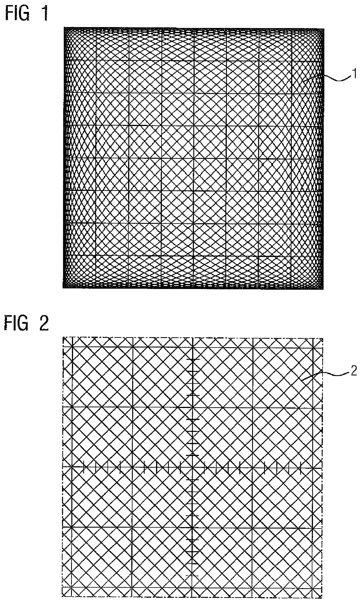
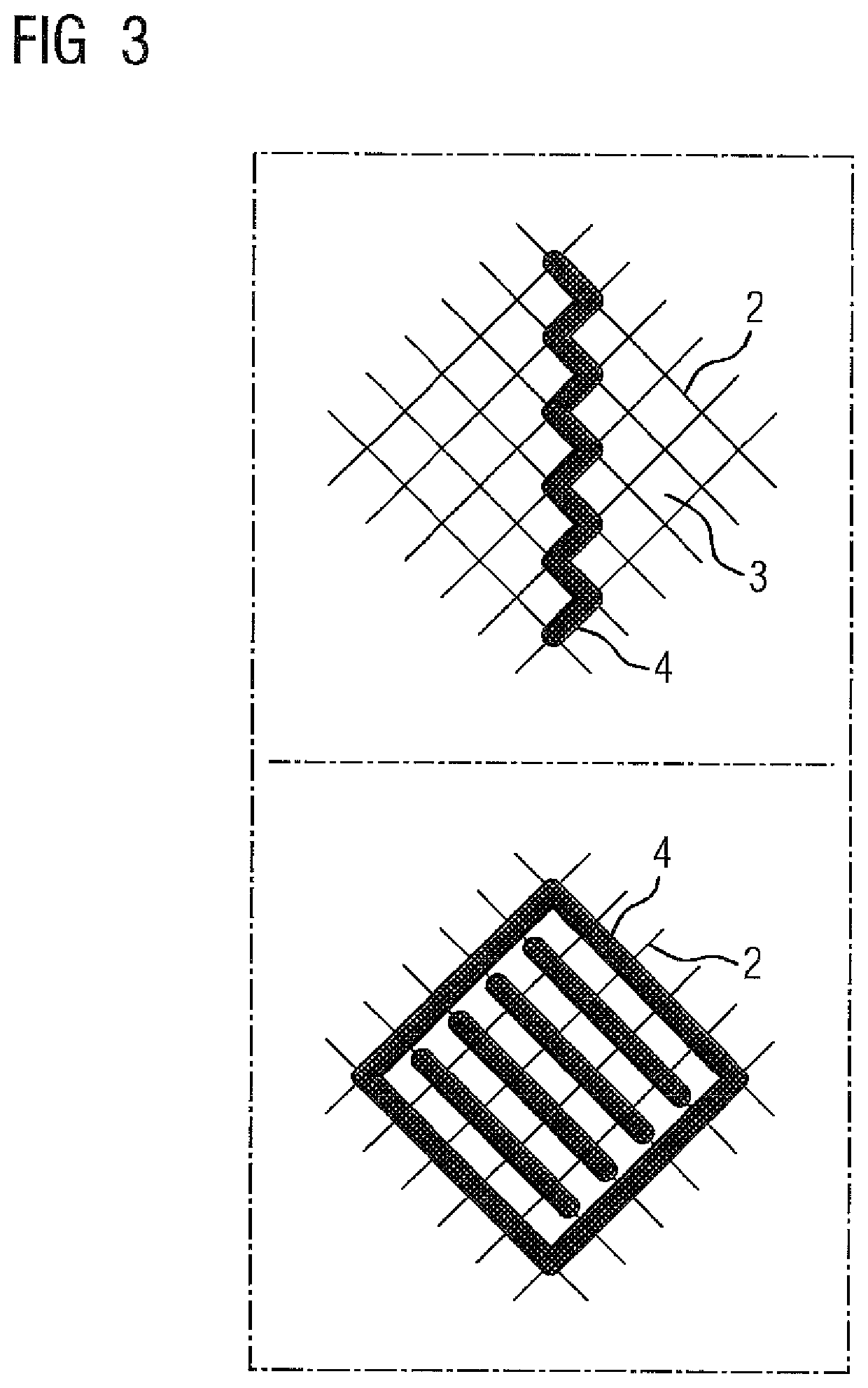
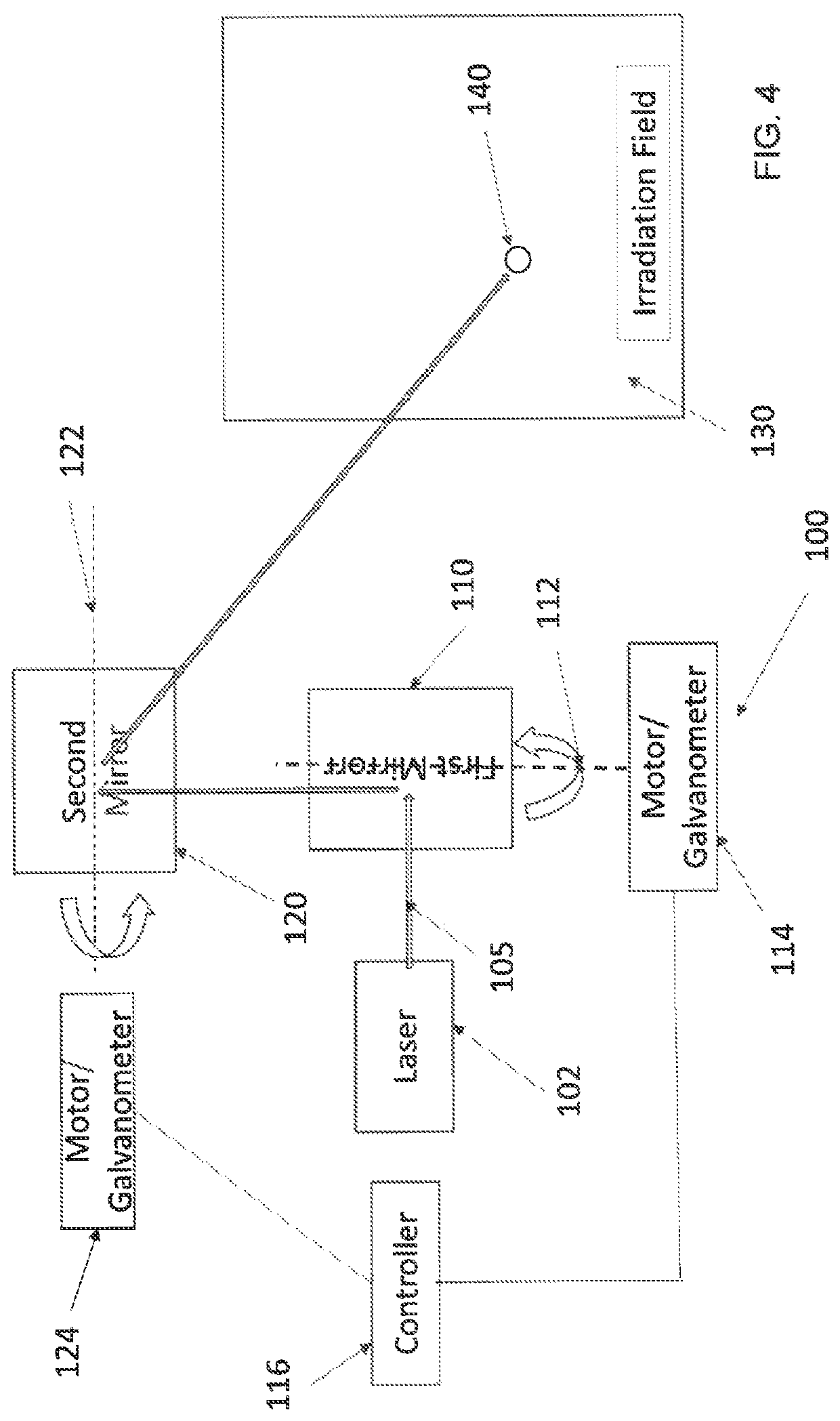
[0045]It has been recognized in accordance with the invention that on the one hand the mechanical inertia of the mirrors or of the mirrors by comparison with the shafts is a first problem. On the other hand the problem lies in the fact that the desired pattern / display pattern in the irradiation field is to be specified in or to be divided into single, individual movements / irradiation points. I.e. the desired irradiation points must be projected onto a default pattern to be illuminated.

[0046]In accordance with the invention it has further been recognized that through the continuous movement of the mirrors of the scanner or of a galvanosco...


PUM

PropertyMeasurementUnit
frequencyaaaaaaaaaa
frequencyaaaaaaaaaa
frequencyaaaaaaaaaa

Abstract

A method and a control device for deflection of a laser beam for laser-based additive manufacturing processes includes first and second orthogonally rotatable mirrors designed to reflect the laser beam and guide the laser beam to an irradiation field. The first mirror and the second mirror are secured on respective first and second shafts, with the first mirror performing a continuous first vibration with a first frequency, and the second mirror performing a continuous second vibration with a second frequency different from the first frequency and/or with a phase difference with respect to the first vibration. Each of the two shafts has a known position such that the first vibration is synchronous with the second vibration. The laser is activated/deactivated upon reaching/leaving an irradiation point. The generated vibrations of the mirrors describe a continuous Lissajous curve.

Description

CROSS-REFERENCES TO RELATED APPLICATIONS[0001]This application is the U.S. National Stage of International Application No. PCT / EP2016 / 072011, filed Sep. 16, 2016, which designated the United States and has been published as International Publication No. WO 2017 / 055110 and which claims the priority of European Patent Application, Ser. No. 15187522.6, filed Sep. 30, 2015, pursuant to 35 U.S.C. 119(a)-(d).BACKGROUND OF THE INVENTION[0002]The invention relates to a control device for laser beam deflection for the processing of irradiation points in an irradiation field by means of a laser beam for laser-based additive manufacturing processes, having at least one first and one second orthogonally rotatable vertical mirror, via which the laser beam can be reflected, for guiding the laser beam to the irradiation field, and wherein the first mirror is secured on a first shaft and wherein the second mirror is secured on a second shaft. The invention further relates to a method for controllin...

Claims


Application Information

Patent Timeline
Patent Type & Authority Patents(United States)
IPC IPC(8): B23K26/04G02B26/08B23K26/082B23K26/342B29C67/04B23K26/144B22F3/105G02B26/10B22F10/00B22F10/10
CPCB23K26/043B22F3/105B23K26/082B23K26/0821B23K26/144B23K26/342B29C67/04G02B26/0816B22F10/00B22F10/10G02B26/101Y02P10/25B22F10/366B22F12/49B22F10/28B22F10/12
Inventor DÜRR, MATTHIAS
Owner SIEMENS AG
Why Eureka
Try Eureka