Touch panel and display device

a display device and touch panel technology, applied in the field of touch panel and display device, can solve the problems of inability to inspect the lead line of the y electrode or the disconnection of the y electrode, and achieve the effect of narrowing the width of the picture frame outside the effective touch region

Active Publication Date: 2011-10-27
PANASONIC LIQUID CRYSTAL DISPLAY CO LTD +1
View PDF8 Cites 38 Cited by
  • Summary
  • Abstract
  • Description
  • Claims
  • Application Information

AI Technical Summary

Benefits of technology

[0018]To briefly explain advantageous effects acquired by the representative inventions among the inventions described in this specification, it is as follows.
[0019]According to the present invention, in a touch panel where inspection pads a

Problems solved by technology

On the other hand, the omission of the inspection pads for narrowing the picture frame gives rise to a dr

Method used


Image

  • Touch panel and display device
  • Touch panel and display device
  • Touch panel and display device

Examples


embodiment 1

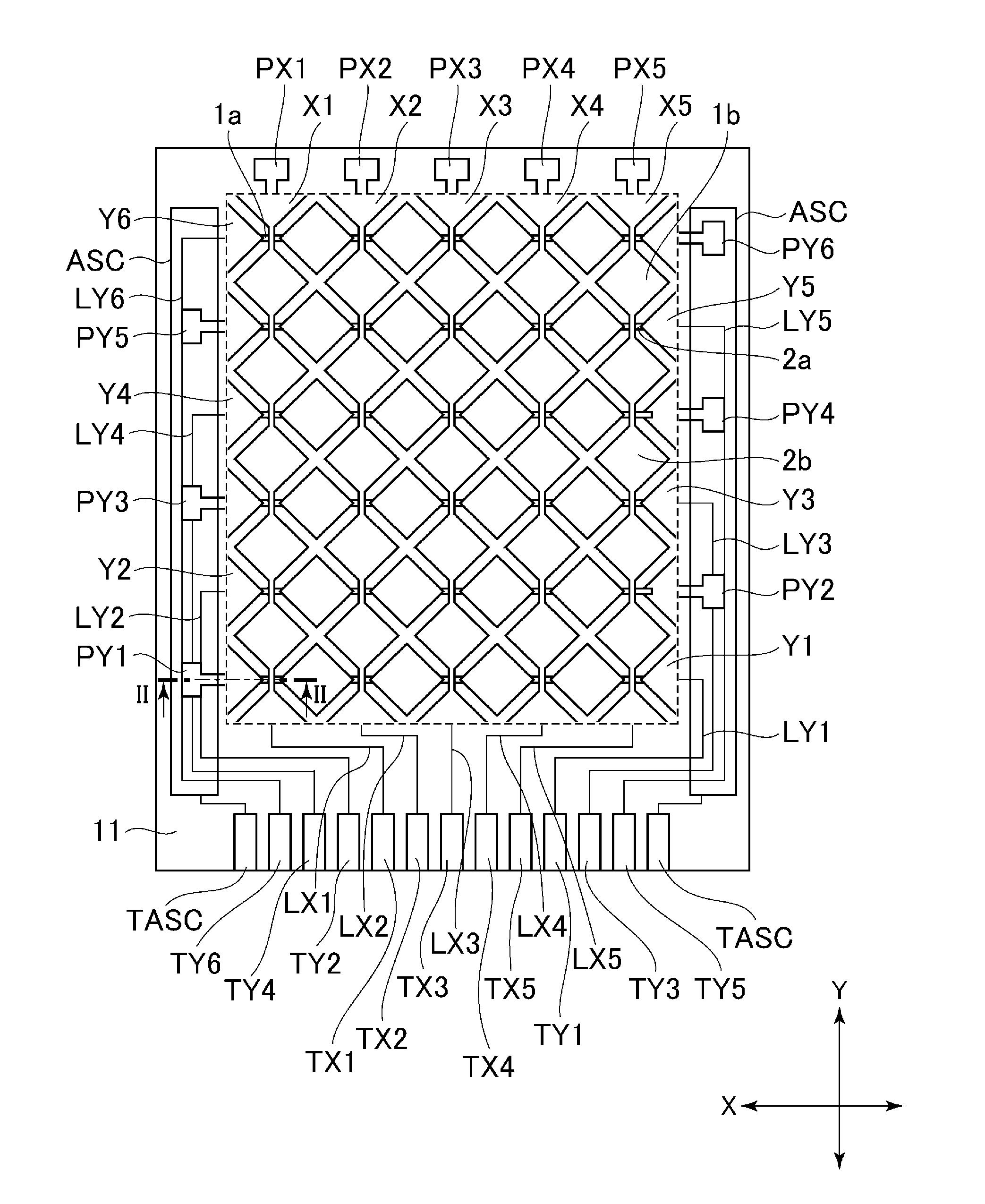
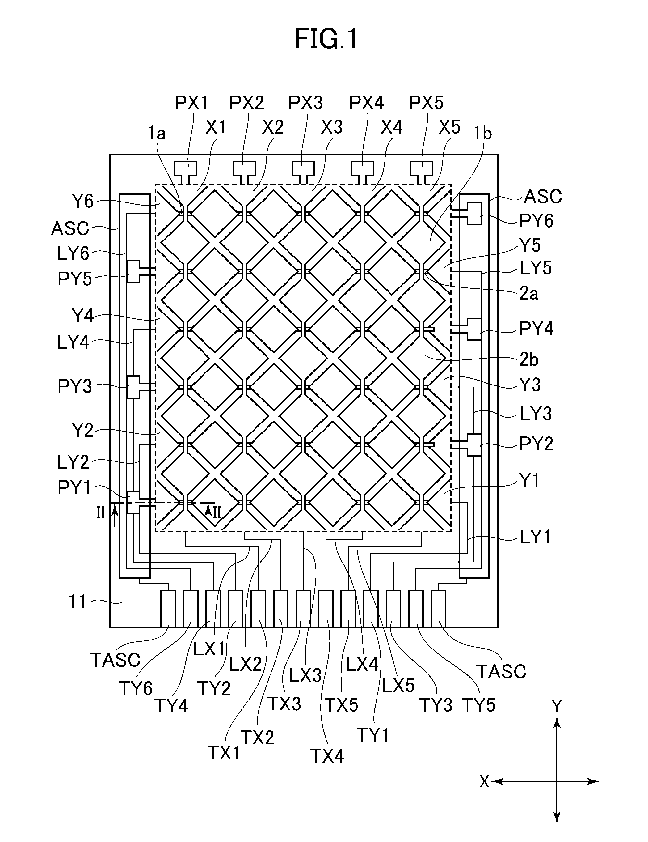
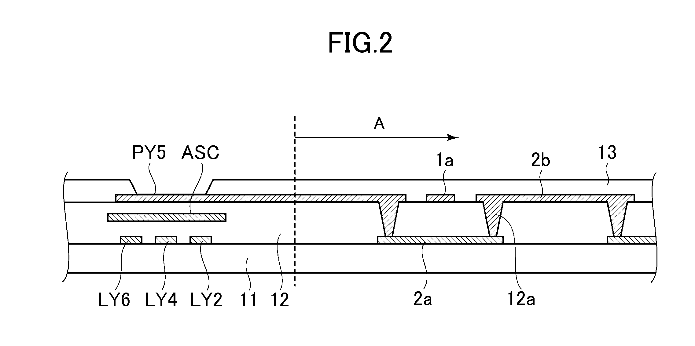
[0034]FIG. 1 is a view for explaining a touch panel according to the embodiment 1 of the present invention, and FIG. 2 is a cross-sectional view of an essential part showing the cross-sectional structure of the touch panel taken along a line II-II in FIG. 1.

[0035]As shown in FIG. 1, the touch panel of this embodiment includes a plurality of X electrodes (X1 to X5) which extend in a second direction (Y direction) and are arranged parallel to each other in a first direction (X direction) which intersects with the second direction at a predetermined arrangement pitch, and a plurality of Y electrodes (Y1 to Y6) which extend in the first direction intersecting with the X electrodes and are arranged parallel to each other in the second direction at a predetermined arrangement pitch. A portion indicated by a dotted frame in FIG. 1 indicates an effective touch region.

[0036]Each one of the plurality of X electrodes has an electrode pattern in which a fine line portion 1a and a pad portion 1b...

embodiment 2

[0065]FIG. 3 is a view for explaining a touch panel according to an embodiment 2 of the present invention, and FIG. 4 is a cross-sectional view of an essential part showing the cross-sectional structure of the touch panel taken along a line IV-IV in FIG. 3.

[0066]This embodiment is characterized in that inspection pads (PY1 to PY6) are formed outside terminal portions (TX1 to TX5, TY1 to TY6) formed on one side of a substrate where the terminal portions are formed, and inspection-use lead lines (LPY1 to LPY6) are connected between the inspection pads (PY1 to PY6) and the other end portions of Y electrodes.

[0067]The inspection-use lead lines (LPY1 to LPY6) are formed over the same layer over which fine line portions 1a and pad portions 1b of X electrodes and pad portions 2b of the Y electrodes are formed, and the inspection-use lead lines (LPY1 to LPY6) are formed of a transparent conductive film made of ITO or the like in the same manner as the X electrodes and the Y electrodes. Due ...

embodiment 3

[0079]FIG. 8 is a view for explaining an X electrode of a touch panel according to an embodiment 3 of the present invention. This electrostatic-capacitance type touch panel determines presence or non-presence of a finger touch based on a change in capacitance of the X electrode or a Y electrode in response to the finger touch. Sensitivity in such an operation is influenced by capacitances and resistances of the X electrode and the Y electrode per se. That is, when the capacitances are large, it is impossible to grasp the change in capacitance when a user touches the touch panel. When the resistances are large, the electrodes (X electrode and Y electrode) cannot be charged sufficiently and hence, a response value for the finger touch becomes small so that sensitivity is lowered.

[0080]Further, when the reaction value in response to the finger touch fluctuates within an effective touch region, a region where sensitivity is insufficient is formed partially and such a region adversely in...


PUM


Abstract

Provided is an electrostatic capacitance type touch panel in which lead lines are alternately connected to one end portions of a plurality of Y electrodes, the respective lead lines are formed outside an effective touch region, and are connected to terminals which are formed corresponding to the respective lead lines, inspection pads which are connected with the Y electrodes respectively are formed over end portions of the respective Y electrodes on a side where the lead lines are not connected to the respective Y electrodes, the plurality of inspection pads are formed in a region where the lead lines are formed outside the effective touch region, a shield electrode is provided between the lead lines and the respective inspection pads, and a voltage equal to a drive voltage supplied to the Y electrodes is supplied to the shield electrode.

Description

[0001]The present application claims priority from Japanese application JP 2010-098419 filed on Apr. 22, 2010, the content of which is hereby incorporated by reference into this application.BACKGROUND OF THE INVENTION[0002]1. Field of the Invention[0003]The present invention relates to a touch panel and a display device, and more particularly to a technique which is effectively applicable in narrowing a width of a picture frame region outside an effective touch region.[0004]2. Description of the Related Art[0005]A display device which is provided with a device for inputting information with a touch operation using a finger of a user or a pen (contact pushing operation, hereinafter simply referred to as “touch”) on a display screen (hereinafter also referred to as a touch sensor or a touch panel) is used in a mobile electronic device such as a PDA or a portable terminal, various household appliances, an automated teller machine and the like.[0006]As such a touch panel, a resistance-f...

Claims


Application Information

Patent Timeline
IPC IPC(8): G06F3/045
CPCG06F2203/04107G06F3/044G06F3/0445G06F3/0446
Inventor NISHITANI, SHIGEYUKIANNO, KOUICHI
Owner PANASONIC LIQUID CRYSTAL DISPLAY CO LTD
Why Eureka
Try Eureka