ADAPTIVE IMAGE PROCESSING METHOD AND APPARATUS FOR REDUCED COLOUR SHIFT IN LCDs

a technology of image data and adaptive processing, which is applied in the field of adaptive image processing methods and apparatuses for processing image data for display, can solve the problems of affecting the effect of the image, affecting the quality of the image, and the colour shift with the viewing angle remains a problem for many types of lcd, so as to reduce computing and memory resources, improve the effect of colour shift, and avoid any sharp changes in off-axis luminan

Inactive Publication Date: 2011-10-27
SHARP KK
View PDF3 Cites 7 Cited by
  • Summary
  • Abstract
  • Description
  • Claims
  • Application Information

AI Technical Summary

Benefits of technology

[0090]Of course, a single LUT may be calculated which incorporates the output values for each input value which result in the off-axis luminance plot described by the bold line in the figure. A key advantage of the present invention is that the analysis step preceding the LUT selection step effectively allows the points at which the output values “hop” from one LUT plot to another to be shifted in dependence on the data values of the other colour components in the pixel being modified, providing greatly increased scope for optimising the preservation of a wider range of colours and increased maximum brightness.
[0091]If the reduced computing and memory resource required by a method which only uses a single LUT to provide the off-axis to on-axis luminance characteristic shown by the bold line in FIG. 10 is desirable, then the output values of the LUT may be calculated using the following method which is based on that disclosed in the co-pending application GB 0916241.3 for use in a privacy type display. The on-axis and off-axis (e.g. at 50° inclination) luminance of the display may be measured for all input data values, or indeed for a selection of the possible data values and the remainder interpolated, of a particular colour channel. From this data, the average combined average off-axis and on-axis luminance for all possible combinations of data values on two pixels of that colour may be inferred. If these values are normalised, and each combination plotted as a point in off-axis to on-axis luminance space, the result is as shown in FIG. 17 (a).
[0092]A series of these points can be selected according to the required on-axis and off-axis luminance for each input data value of the LUT. FIG. 17 (b) shows the same population of available average on-axis and off-axis luminance points for the pixel data combinations, with a bold black line joining the points which have been selected for the LUT. In this case, the points have been selected to provide an normalised on-axis luminance for each input data value which is as close to the normalised on-axis luminance which the input data value would itself produce, and a normalised off-axis luminance which is as close as possible to the normalised on-axis luminance, while avoiding any sharp changes in off-axis luminance between points with similar on-axis luminance, which would cause image artefacts to the off-axis viewer. Any off-axis to on-axis luminance trace within the space of available points may be selected but traces of the form shown in FIG. 17(b) have been shown to provide good colour shift improvement. The output values of the LUT can then be determined as being the combination of two data values which produced each selected point of FIG. 17(b). This method may be performed for each colour channel of the display, providing a means to achieve good colour shift improvement with only one LUT required for each colour channel, each LUT consisting of a pair of output data values for each input data value.
[0093]After the analysis, LUT selection and data modification steps have been performed on all pixel data values in the input image, the modified image is output from the modified display control electronics to the display. An example process flow diagram for performing the steps described above is given in FIG. 11. The process flow may be implemented via hardware, software stored in computer-readable memory such as read-only memory or the like, or a combination thereof and may be implemented, for example, in the Control ASIC of the control electronics represented in FIG. 1. Those having ordinary skill in the art of computer software and / or hardware design for LCD displays will readily appreciate based on the description provided herein how to provide software and / or hardware to carry out the functions described herein without undue effort or experimentation. Accordingly, further detail as to the particular arrangement has been omitted herein for the sake of brevity.
[0094]FIG. 11 exemplifies how initial RGB pixel data constituting an image is received by the Control ASIC, processed in accordance with the invention, and output as modified R′G′B′ pixel data. Specifically, the initial RGB data serves as indexing values to the plurality of LUTs discussed herein. The output values from each of the LUTs are input to a multiplexer. The particular LUTs from which output values are selected are determined in part based on the output of a Data Analysis block and Register block. The initial RGB data is analyzed by a Data Analysis block in accordance with the analysis described herein so as to identify the top colour component having the highest data level and the (h−m) value. The output of such analysis is provided to the selection input of the multiplexer. The Register block stores the (h−m) threshold values as represented, for example, in FIG. 7. These threshold values are also provided to the selection input of the multiplexer such that, in conjunction with the top colour component and (h−m) value, the corresponding LUT(s) which provide the modified R′G′B′ image data is selected. Within the selected LUT(s), which particular output value is selected is dependent on a spatial parameter, also provided to a selection input of the multiplexer, based on the position of the pixel or sub-pixel being modified in the image to be displayed. The modified image data from the selected output of the selected LUT(s) is then provided to the source driver ICs and presented to each corresponding pixel.
[0095]It has been found that in the selection step, the h−m parameter provides a simple and effective method of determining which LUT will provide the optimum reduction in colour shift when the modified values for the middle and lower colour component are retrieved from it. However, any other means of analysis of the input pixel values which provides the required differentiation between input colours requiring different output modifications to optimally reduce colour shift may be employed.

Problems solved by technology

Despite significant advances in liquid crystal display (LCD) technology, resulting in very high performance displays with improved metrics such as display area, brightness, image contrast, resolution, colour gamut, bit-depth, response time and wide view performance, colour shift with viewing angle remains a problem for many types of LCD.
As a result of this fixed relationship, both of the above approaches in pixel hardware and display software or control electronics suffer from the limitation that in order to optimally reduce the colour shift with viewing angle of the display, the effective pixel brightness observed by the on-axis viewer has to be composed of two or more regions of different brightness, for all but the off state (zero voltage applied to all regions).
Both regions, either the plurality of regions within a split colour sub-pixel, or neighbouring whole colour sub-pixels which have been subject to a transfer of luminance within local groups, therefore cannot be fully bright without compromising the effectiveness of the method in reducing the colour shift.
However, it is the inherent property of liquid crystal displays that their electro-optic response is angularly dependent and the off-axis gamma curve will differ from the on-axis one, and while contrast inversion problems have largely been solved with multidomain pixels and improved compensation films, colour shift with angle remains a problem.
This will reduce the effectiveness of the colour shift reduction effect however.

Method used


Image

  • ADAPTIVE IMAGE PROCESSING METHOD AND APPARATUS FOR REDUCED COLOUR SHIFT IN LCDs
  • ADAPTIVE IMAGE PROCESSING METHOD AND APPARATUS FOR REDUCED COLOUR SHIFT IN LCDs
  • ADAPTIVE IMAGE PROCESSING METHOD AND APPARATUS FOR REDUCED COLOUR SHIFT IN LCDs

Examples


Embodiment Construction

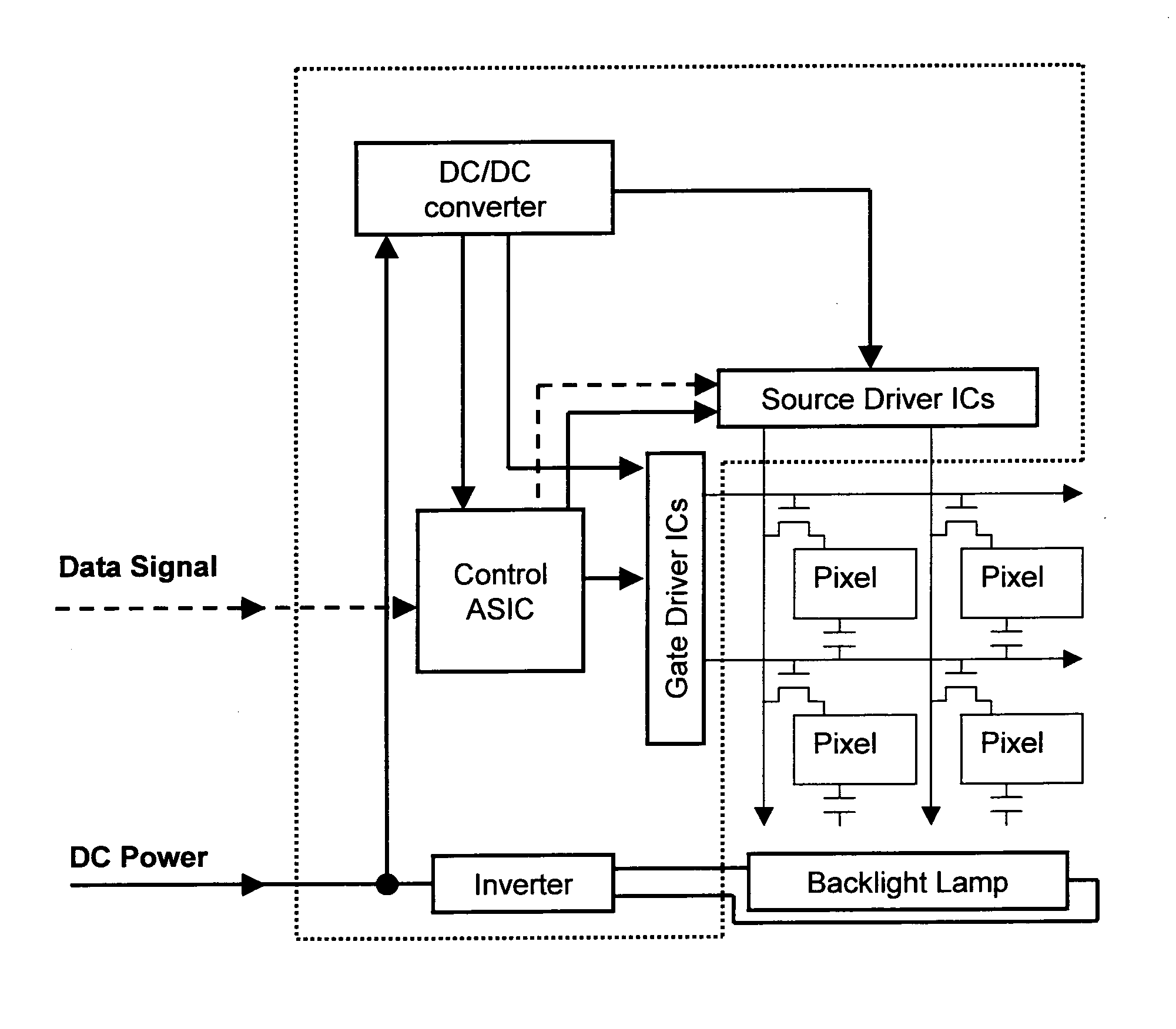
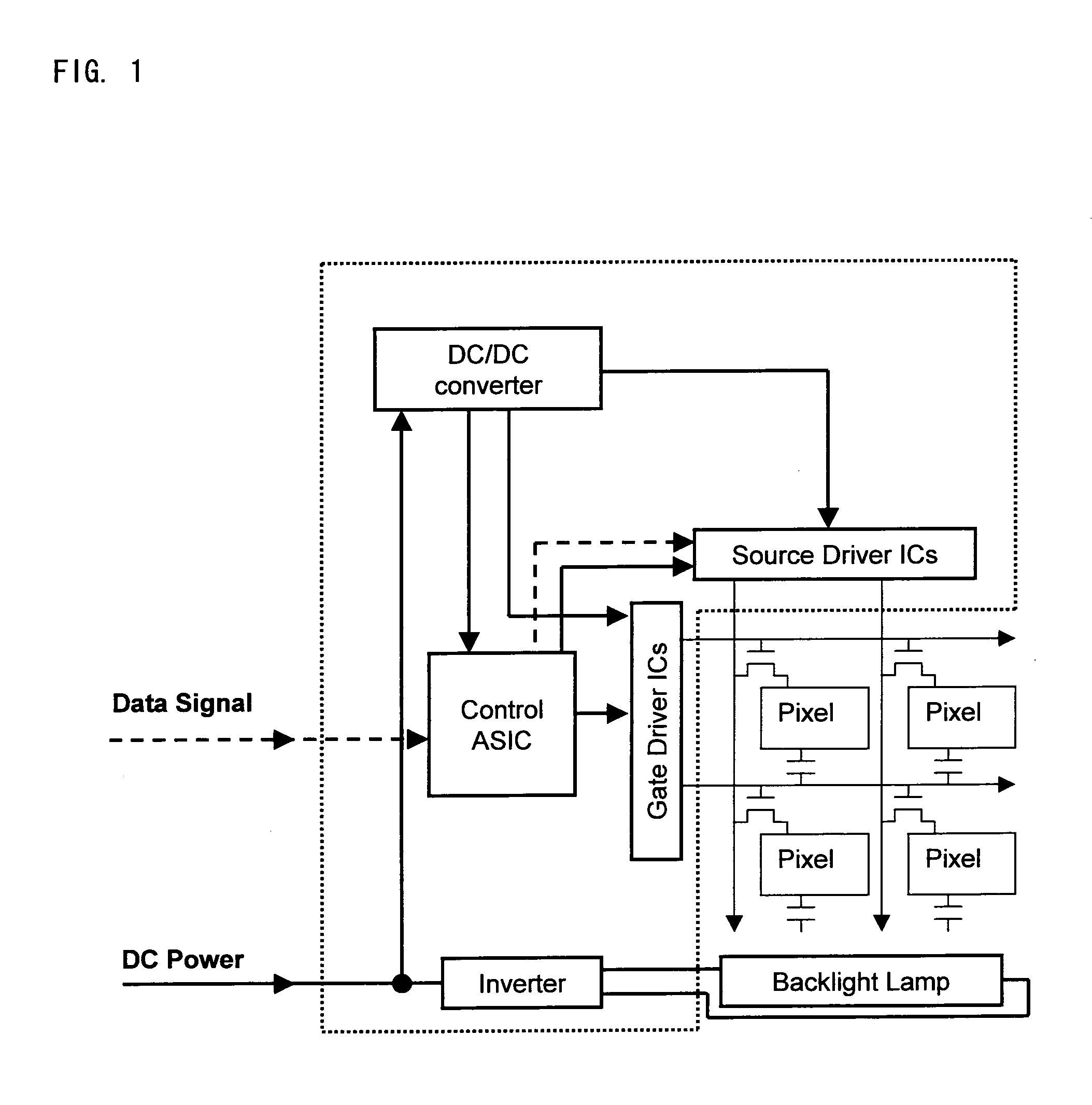
[0076]In an exemplary embodiment of a display in accordance with the present invention, the display includes a standard LCD display, an example of which is illustrated in FIG. 1, with modified control electronics.

[0077]When such a display is operating in a standard manner, a set of main image data constituting a single image is input to the control electronics in each frame period, typically in the form of a serial bit stream. The control electronics then outputs a set of signal data voltages to the LC panel. Each of these signal voltages is directed by the active matrix array of the LC panel to the corresponding pixel electrode and the resulting collective electro-optical response of the pixels in the LC layer generates the image.

[0078]As described above, in displays including a colour shift reduction technology, the image data can be modified in the control electronics, the driver circuitry, or the in-pixel electronics so that each pixel of image data received results in multiple ...


PUM


Abstract

A method and apparatus is provided for reducing colour shift in relation to viewing angle in an LCD. The method includes receiving a plurality of pixel data constituting an image, each pixel data including a plurality of sub-pixel colour components having respective data values; for each of the pixel data, comparing the sub-pixel colour component data values included therein; and based on the comparison, modifying the sub-pixel colour component data values included in the pixel data with respect to two or more of the plurality of sub-pixel colour components to reduce colour shift when displayed on the LCD.

Description

[0001]This application claims priority under 35 USC §119(e) to U.S. Provisional Application No. 61 / 138,594 filed on Dec. 18, 2008, the entire disclosure of which is incorporated herein by reference.TECHNICAL FIELD[0002]The present invention relates to a method of and apparatus for processing image data for display by a display device.BACKGROUND ART[0003]Despite significant advances in liquid crystal display (LCD) technology, resulting in very high performance displays with improved metrics such as display area, brightness, image contrast, resolution, colour gamut, bit-depth, response time and wide view performance, colour shift with viewing angle remains a problem for many types of LCD.[0004]In order to improve the wide-view performance of LCDs, several technologies have been developed. Displays have been produced with angular compensation films such as the splayed-discotic Wide-View film for Twisted Nematic (TN) displays, multidomained pixels for Vertically Aligned Nematic (VAN) an...

Claims


Application Information

Patent Timeline
Patent Type & Authority Applications(United States)
IPC IPC(8): G09G5/02
CPCG09G3/2018G09G3/3607G09G3/3648G09G2360/16G09G2320/0666G09G2320/0673G09G2320/068G09G2320/0242
Inventor BROUGHTON, BENJAMIN JOHNWALTON, HARRY GARTHGASS, PAUL ANTONYLOOTUS, MEELISBORGERS, CHARLOTTE WENDY MICHELE
Owner SHARP KK
Why Eureka
Try Eureka