Display apparatus

Active Publication Date: 2011-10-27
LG DISPLAY CO LTD
View PDF2 Cites 69 Cited by
  • Summary
  • Abstract
  • Description
  • Claims
  • Application Information

AI Technical Summary

Benefits of technology

[0009]An object of the present invention is to provide a display apparatus that is able to minimize a thickness by innovatively removing a case and some portions of a set cover, which have

Problems solved by technology

Thus, there has been a limitation to the slimness of the display apparatus and the development of new designs.
Such a structure arrangement increases the thickness of the liquid crystal display apparatus, and

Method used


Image

  • Display apparatus
  • Display apparatus
  • Display apparatus

Examples


first embodiment

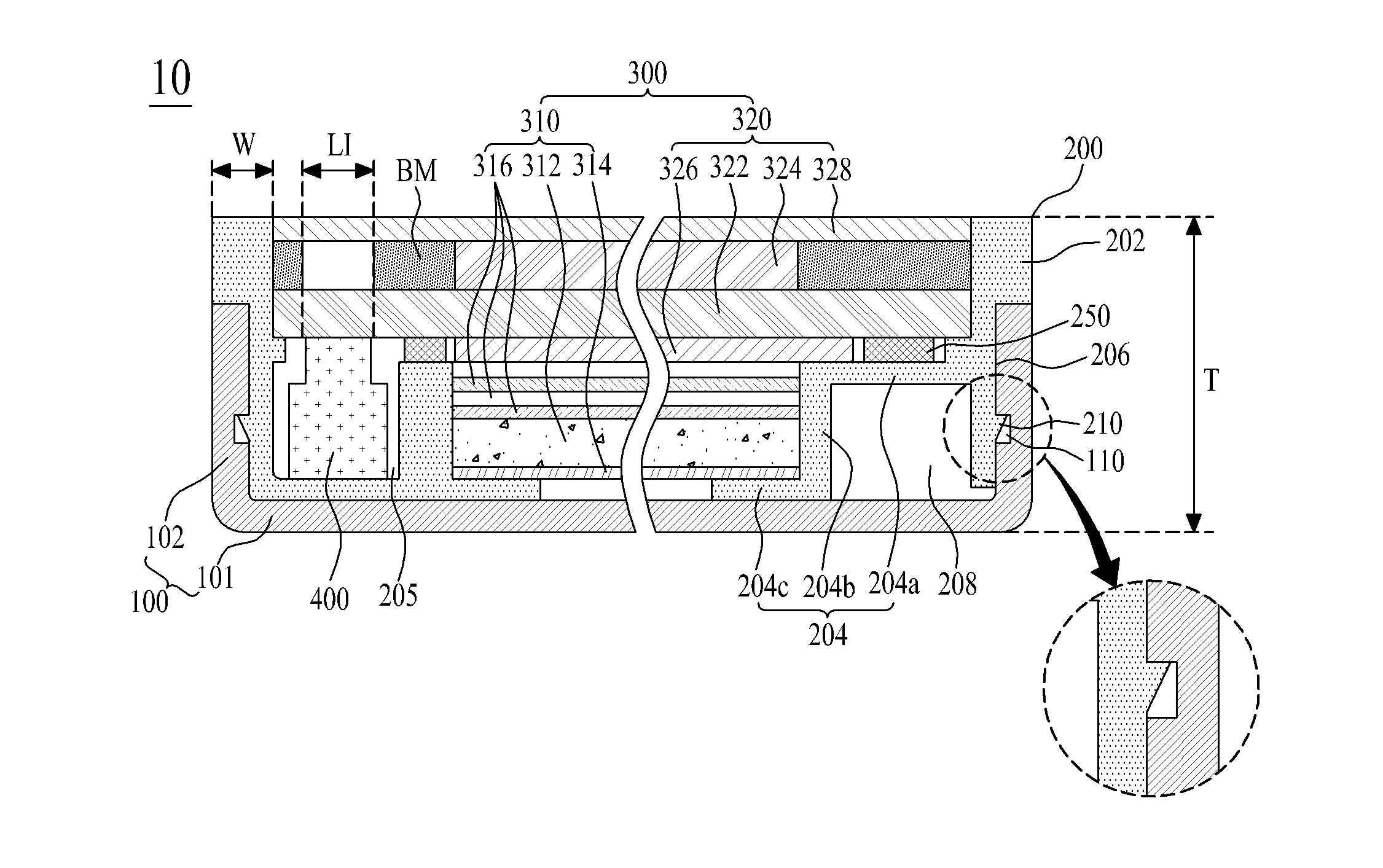
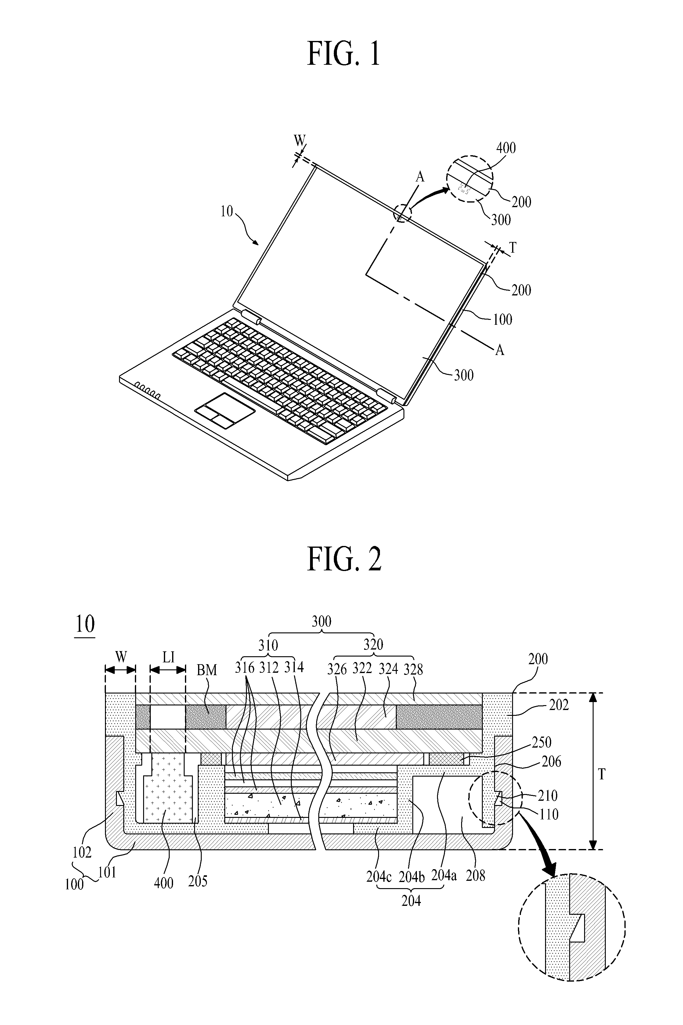
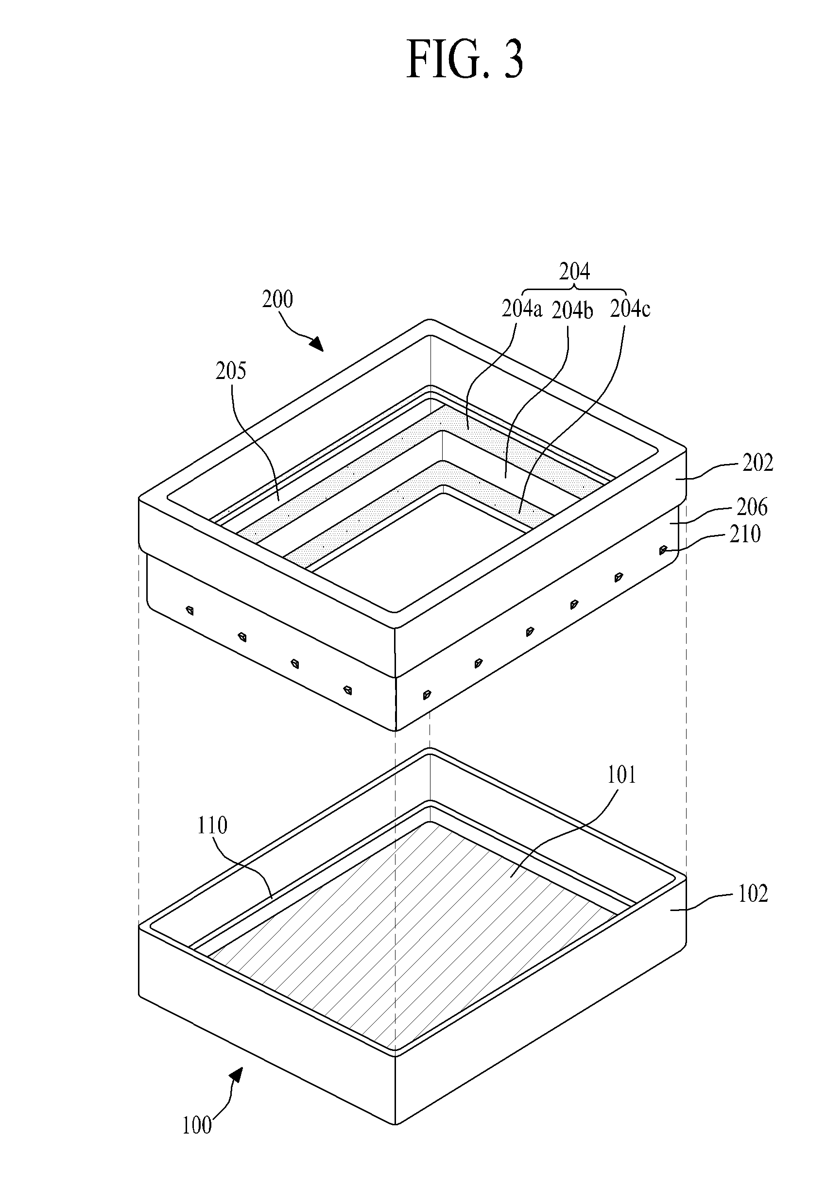
[0054]FIG. 1 illustrates a camera-embedded display apparatus used for a notebook computer according to an exemplary embodiment of the present invention. FIG. 2 is a cross section view along A-A of FIG. 1, which illustrates the camera-embedded display apparatus according to the present invention. FIG. 3 is a perspective view illustrating a set cover and a guide frame of the display apparatus shown in FIG. 2.

[0055]Referring to FIGS. 2 and 3, a display apparatus 10 according to the first embodiment of the present invention includes a set cover 100, a guide frame 200, a display unit 300, and a camera 400.

[0056]The set cover 100 may be formed in a rectangular-shaped frame. The set cover 100 supports the guide frame 200 and the display unit 300, and simultaneously covers a lateral side of the guide frame 200, whereby the set cover 100 functions as a cover of the manufactured display apparatus 10. In this case, the set cover 100 may be formed of a plastic material or a metal material. For ...

second embodiment

[0084]FIG. 5 is a cross section view schematically illustrating a display apparatus according to the present invention.

[0085]Referring to FIG. 5, the display apparatus 10 according to the second embodiment includes a set cover 100, a guide frame 200, a display unit 300, a camera 400, and a sealing member 500. Except that a sealing member 500 is additionally provided, the display apparatus 10 according to the second embodiment is identical in structure to the display apparatus according to the first embodiment shown in FIGS. 2 to 4, whereby a detailed explanation for the same parts will be omitted.

[0086]During a process of manufacturing the display unit 300, and more particularly, liquid crystal display panel 320 and guide frame 200, a gap may occur between a lateral side of the liquid crystal display panel 320 and a guide sidewall 202 of the guide frame 200 due to a manufacturing error. Thus, the sealing member 500 may be used to seal the gap between the lateral side of the liquid c...

third embodiment

[0094]FIG. 9 is a cross section view schematically illustrating a display apparatus according to the present invention.

[0095]Referring to FIG. 9, the display apparatus 10 according to the third embodiment includes a set cover 100, a guide frame 200, a display unit 300, a camera 400, and an exposure hole (EH). Except for the exposure hole (EH) that is additionally provided, the display apparatus 10 according to the third embodiment is identical in structure to the display apparatus according to the first embodiment shown in FIGS. 2 to 4, whereby a detailed explanation for the same parts will be omitted.

[0096]The exposure hole (EH) may be formed in a predetermined portion of an upper polarizing plate 328 corresponding to a light-incidence portion (L1) overlapping with a camera-receiving portion 205. Thus, the camera 400 takes a series of photographs of the surroundings through the use of ambient light incident on the light-incidence portion (L1) through the exposure hole (EH) in the u...


PUM


Abstract

A display apparatus, which is able to minimize a thickness by innovatively removing a case and some portions of a set cover and to realize a good aesthetic exterior appearance of the display apparatus by a novel design, includes a set cover exposed to the external to have a storage space, a guide frame received in the storage space, a display unit including a display panel prepared by bonding lower and upper substrates to each other, the display unit placed onto the guide frame, and a camera overlapping with one edge of the display unit and received in the guide frame.

Description

[0001]This application claims the benefit of the Korean Patent Application Nos. 10-2010-0039023 and 10-2010-0039026 filed on Apr. 27, 2010, which are hereby incorporated by reference as if fully set forth herein.BACKGROUND OF THE INVENTION[0002]1. Field of the Invention[0003]The present invention relates to a display apparatus, and more particularly, to a display apparatus that is capable of minimizing a thickness by innovatively removing a case and some portions of a set cover, which have been regarded as indispensable structures for a camera-embedded display apparatus, and simultaneously is capable of realizing a good aesthetic exterior appearance of the display apparatus by a novel design.[0004]2. Background for the Related Art[0005]Recently, various flat-type display apparatuses have been actively developed and researched to reduce heavy weight and large volume caused by the disadvantages of a Cathode Ray Tube (CRT). The flat-type display apparatuses include, but are not limited...

Claims


Application Information

Patent Timeline
IPC IPC(8): G02F1/1333G03B17/48
CPCG02F2001/133314G02F2201/465H04N5/2257G03B29/00G03B17/02G02F1/133314H04N23/57
Inventor KIM, DONG YONGSON, NAM DOYOU, SONG RYOLBAEK, KYEONG TAKKIM, SEONG ROKJEAN, KI NAM
Owner LG DISPLAY CO LTD
Why Eureka
Try Eureka