
Surgical instrument

a surgical instrument and surgical technology, applied in the field of medical devices, can solve the problems of scars, inability to provide the desired level of freedom in microsurgical or spa surgery procedures, and inability to meet the needs of surgical procedures in which only one incision is made, so as to achieve the effect of minimizing the diameter of the instrument and effective mode of “minimally invasive surgery”

Inactive Publication Date: 2011-10-27
ETERNE
View PDF4 Cites 75 Cited by
  • Summary
  • Abstract
  • Description
  • Claims
  • Application Information

AI Technical Summary

Benefits of technology

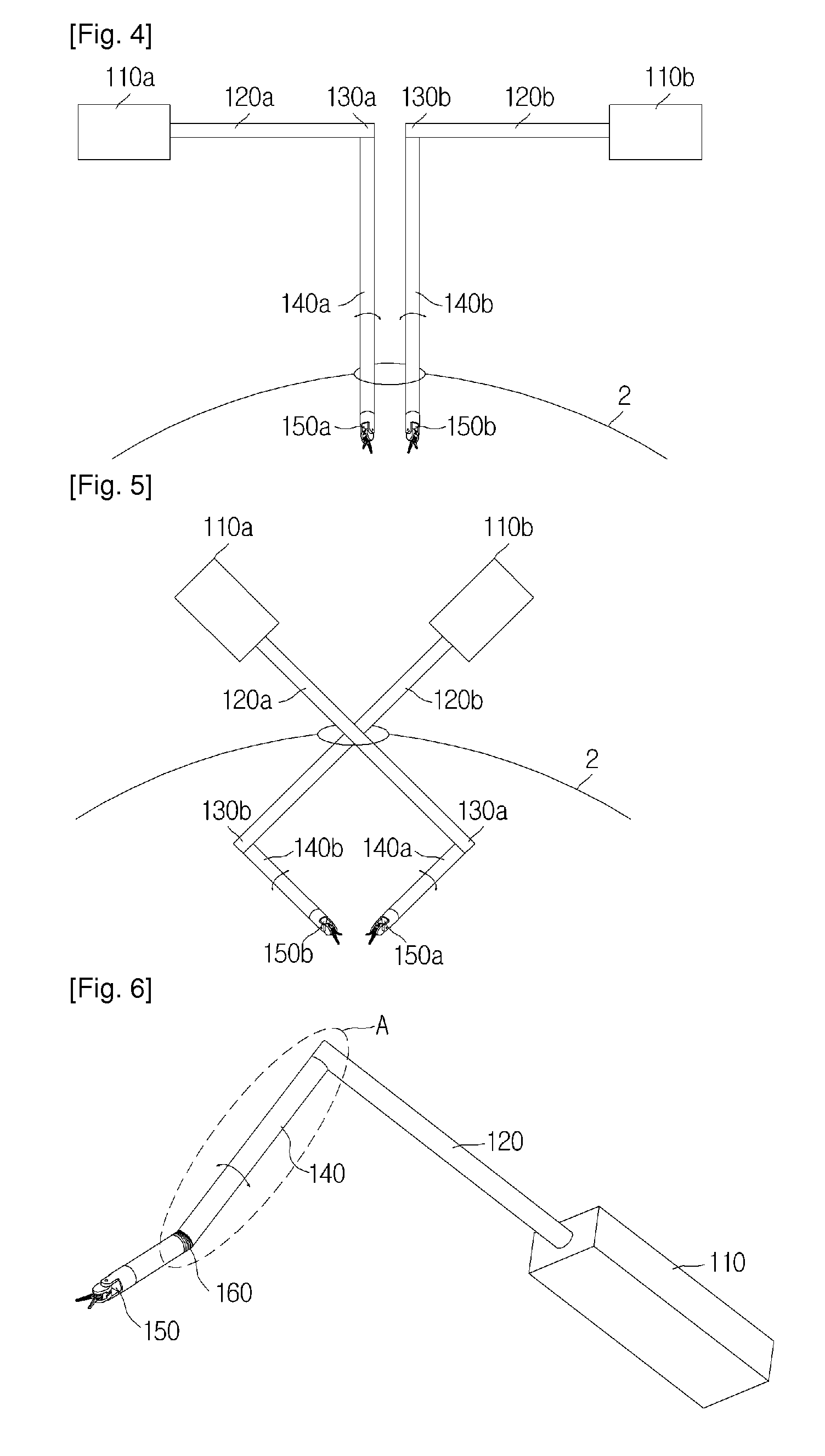
Certain embodiments of the present invention make it possible to conduct surgery using several surgical instruments without having the instruments obstruct one another, and a surgical instrument can be made to have different usage modes according to what length it is set to.
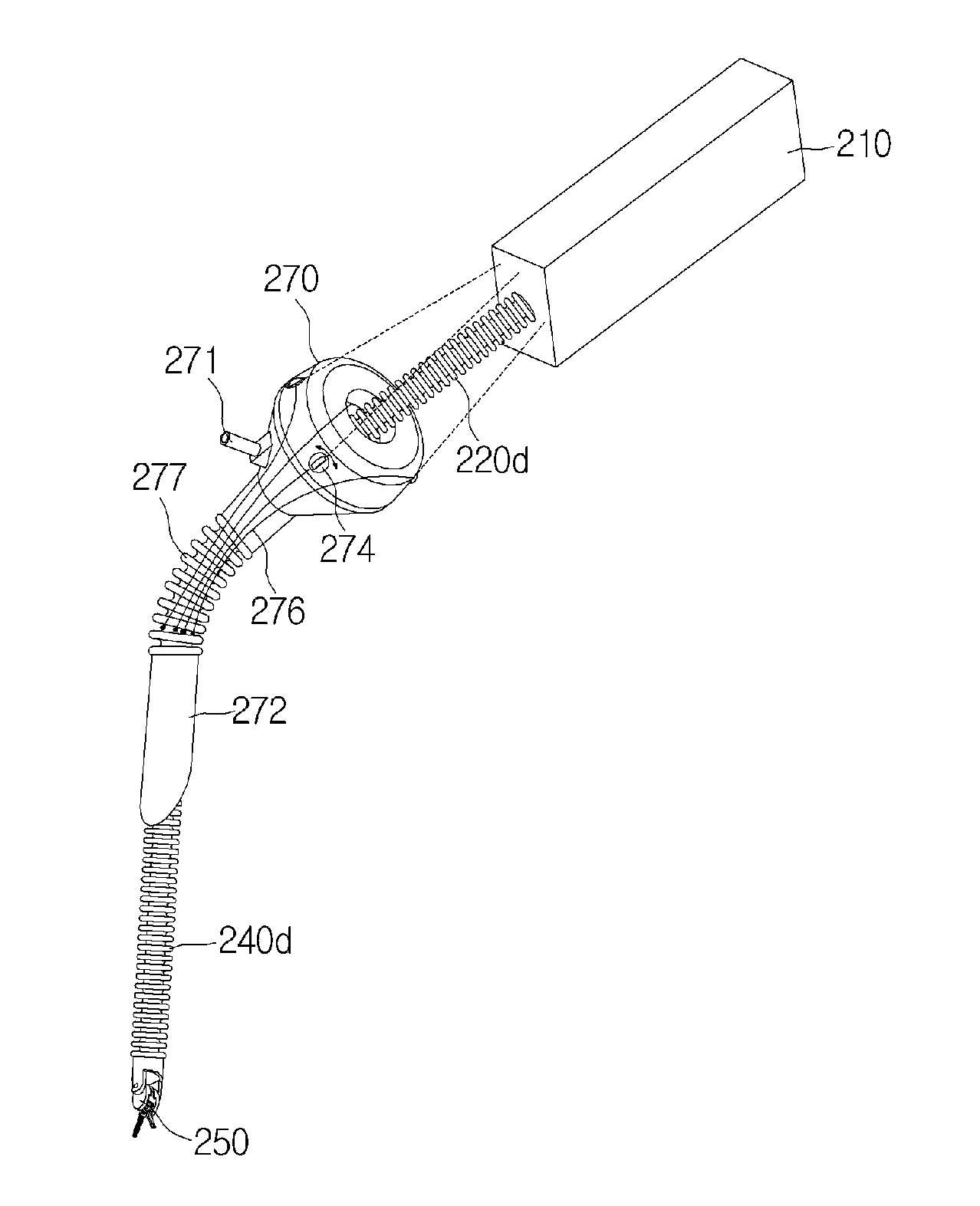
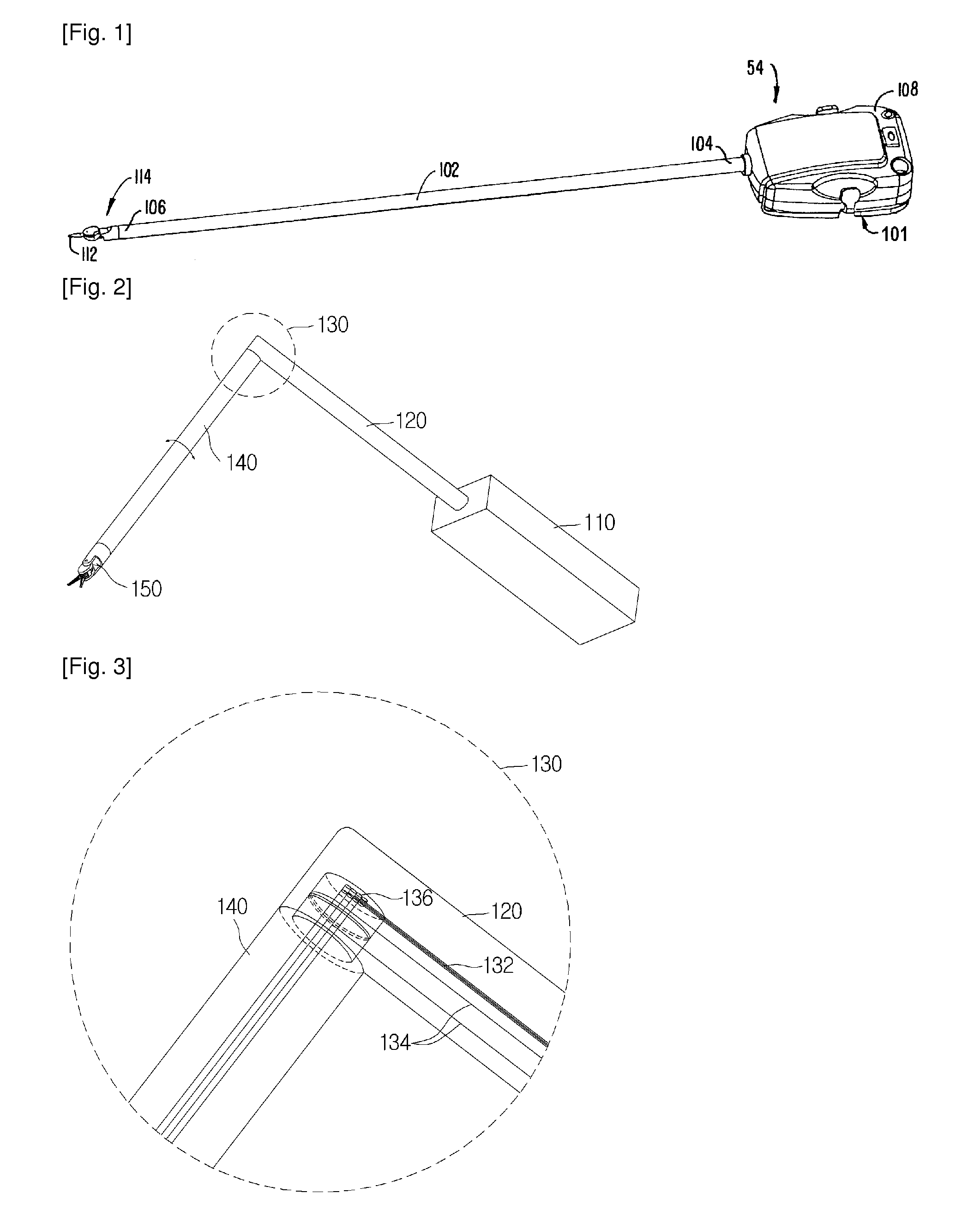
Also, by forming an elbow in the shaft of a surgical instrument and enabling the shaft to bend according to a manipulation on the driving part, the shaft of the instrument can be made to perform articular movements similar to those of a wrist or an elbow. Thus, a surgeon may manipulate the instrument intuitively, just as if the surgeon were using his or her own hands.
Since the shaft of the instrument can be bent as necessary, several instruments can be inserted from different directions through a single insertion hole, and for each instrument, the shaft can be bent such that the effector faces a particular surgical site. Thus, even when using more than one instruments at once, the instruments may not interfere with or obstruct one another, and an effective mode of “minimally invasive surgery” can be implemented.
Also, by forming the effector and a rod to be attachable and detachable in relation to each other, and by forming a multiple number of rods as one set that can be used as a substitute for the shaft, it is possible to minimize the diameter of the instrument. Furthermore, by first inserting the effector into the surgical site, then invading the rod and joining the effector and the rod within the surgical site, it is possible to utilize the surgical instrument after making an incision in the surgical site of a size that does not require suturing.

Problems solved by technology

A surgical procedure such as a laparotomy, etc., in which the skin is cut open and an internal organ, etc., is treated, reconstructed, or excised, may entail problems of blood loss, side effects, pain, and scars.
Although this surgical instrument may be suitable for procedures such as laparoscopic surgery that involve making multiple incisions, it may not be so suitable for surgical procedures in which only one incision is made.
A conventional surgical instrument (including those for robot surgery) may not provide a desired level of freedom in such microsurgery or SPA surgery procedures.
That is, if several of these surgical instruments are placed through one hole or a small slit, the instruments' housings 108, i.e. the couplers, may obstruct one another, making it very inconvenient to use conventional surgical instruments in these types of surgeries.
Also, according to the related art, it can be difficult for a user to utilize a surgical instrument in a convenient and efficient manner, as the user is unable to bend or unbend the shaft 102 at will.
However, for a type of surgery that is performed with just one incision made in the surgical site, such as single port access (SPA) surgery and microsurgery, etc., a conventional surgical instrument may not be used with a high level of freedom, since a laparoscope and the instrument may all be inserted through the one incision for surgery.
However, in the case of a conventional instrument used for laparoscopic surgery, there is a limit to how small the diameter of the shaft can be made, and a trocar may have to be inserted beforehand into the surgical site through which to insert the instrument.

Method used


Image

  • Surgical instrument
  • Surgical instrument
  • Surgical instrument

Examples


Embodiment Construction

As the present invention allows for various changes and numerous embodiments, particular embodiments will be illustrated in the drawings and described in detail in the written description. However, this is not intended to limit the present invention to particular modes of practice, and it is to be appreciated that all changes, equivalents, and substitutes that do not depart from the spirit and technical scope of the present invention are encompassed in the present invention.

While terms including ordinal numbers, such as “first” and “second,” etc., may be used to describe various components, such components are not limited to the above terms. The above terms are used only to distinguish one component from another. For example, a first component can be referred to as a second component without departing from the scope of claims of the present invention, and likewise, a second component can be referred to as a first component. If a component is said to be “connected to” or “accessing” ...


PUM


Abstract

A surgical instrument is disclosed. The surgical instrument, which has an effector for engaging the surgical site joined to one end and a driving part for operating the effector joined to the other end, includes: a first shaft, which has one end joined with the driving part, and which extends along a first lengthwise direction; and a second shaft, which extends along a second lengthwise direction that forms a particular angle with the first shaft, and which has one end joined with the other end of the first shaft such that the second shaft is rotatable about an axis following the second lengthwise direction. Thus, it is possible to conduct surgery using several of such surgical instruments without having the instruments obstruct one another, and the surgical instrument can be made to have different usage modes according to what length it is set to.

Description

TECHNICAL FIELD The present invention relates to a medical apparatus, more particularly to a surgical instrument.BACKGROUND ARTIn the field of medicine, surgery refers to a procedure in which a medical apparatus is used to make a cut or an incision in or otherwise manipulate a patient's skin, mucosa, or other tissue, to treat a pathological condition. A surgical procedure such as a laparotomy, etc., in which the skin is cut open and an internal organ, etc., is treated, reconstructed, or excised, may entail problems of blood loss, side effects, pain, and scars. Thus, current methods of surgery that involve making an incision in the skin and inserting only a medical apparatus, such as a laparoscope, a surgical instrument, and a microscope, for example, or those that involve the use of surgical robots are currently regarded as popular alternatives.A set of surgical robots may include a master robot, which is manipulated by the doctor to generate and transmit the necessary signals, and ...

Claims


Application Information

Patent Timeline
Patent Type & Authority Applications(United States)
IPC IPC(8): A61B17/28
CPCA61B19/2203A61B2017/2901A61B2017/2905A61B2017/2927A61B2017/2929A61B2017/00477A61B2019/2223A61B2019/2242A61B2019/2269A61B2019/2276A61B2019/2211A61B2034/742A61B34/71A61B2034/301A61B34/30A61B34/37A61B34/74
Inventor CHOI, SEUNG WOOKWON, JONG SEOKLEE, JAE SUN
Owner ETERNE
Learn More