Ophthalmologic Implant

Active Publication Date: 2011-10-27
CARL ZEISS MEDITEC AG
View PDF8 Cites 23 Cited by
  • Summary
  • Abstract
  • Description
  • Claims
  • Application Information

AI Technical Summary

Benefits of technology

[0004]Furthermore, it is an object of the present invention to provide a microscopic system and an optical verification method for detecting the posture and position and/or for identification

Problems solved by technology

However, it is disadvantageous in such illuminations that they can only be relatively expensively realized.
However, the known intraocular lenses with marks are disadvantageous in that with permanently visible marks, the effective pupil aperture of the patient and in particular the light transmission of the implant in the visual spectral range are considerably restricted on the one hand.
In addition, transmission modulations near the pupil of the eye can result in undesired photic phenomena by diffraction effects (phase disturbance e.g. at the edges).
On the other hand, even with use of dyes fluorescing in the

Method used


Image

  • Ophthalmologic Implant
  • Ophthalmologic Implant
  • Ophthalmologic Implant

Examples


Example

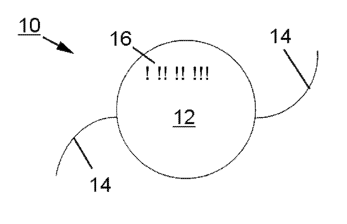
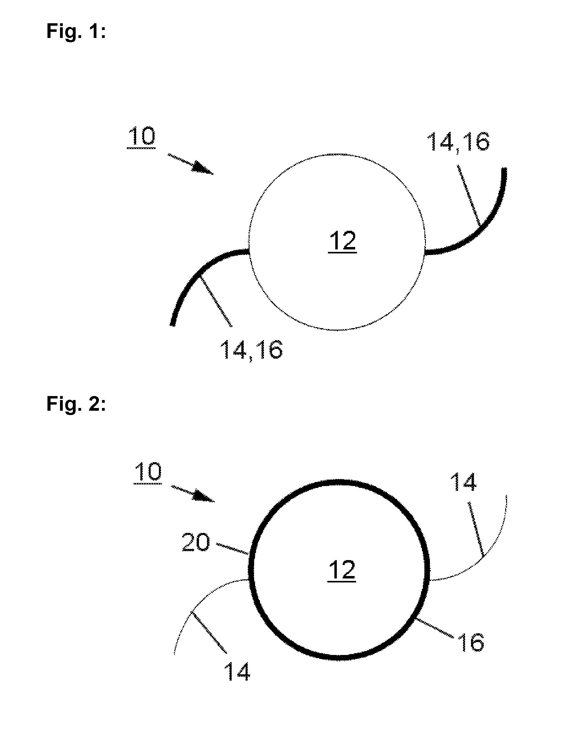
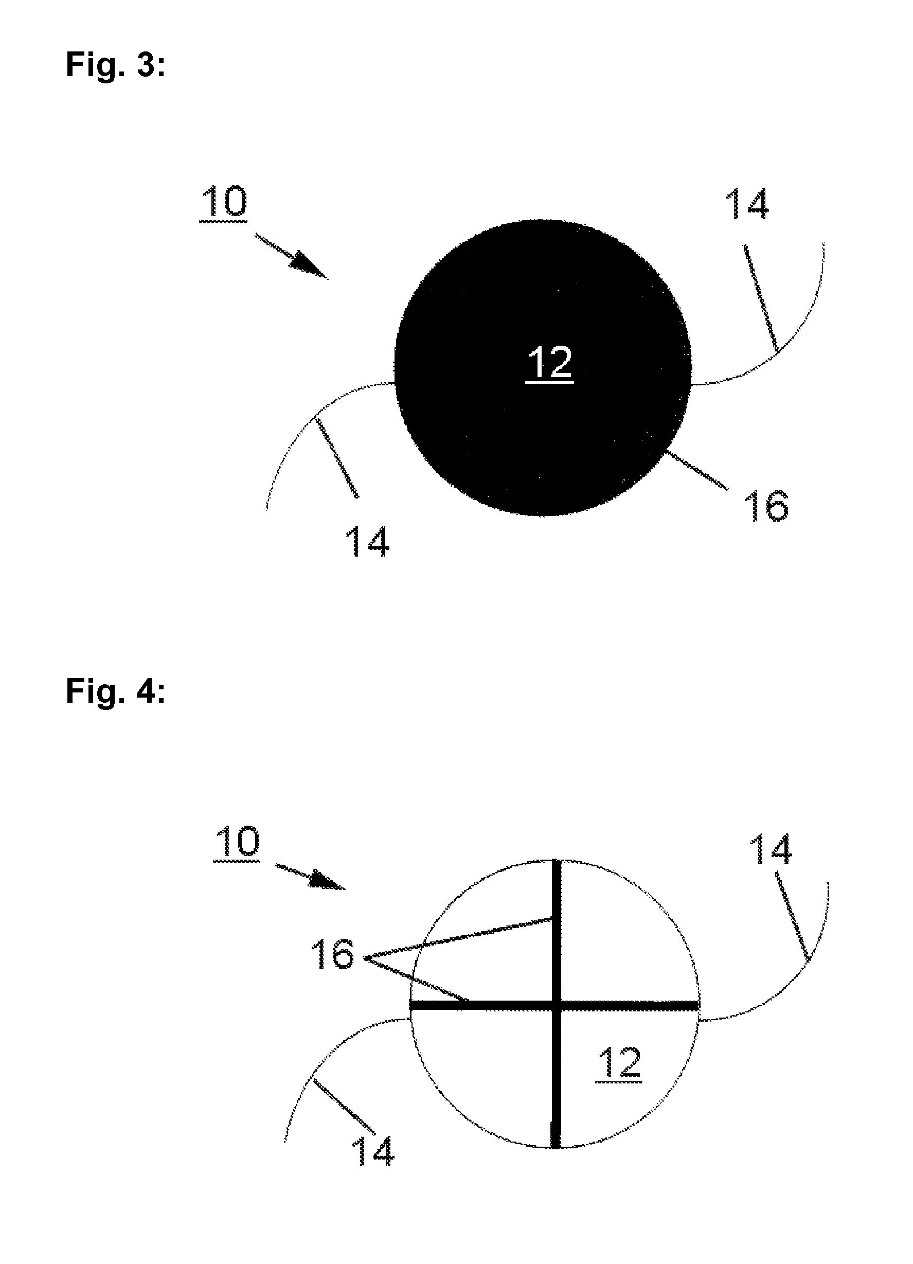
[0033]In a schematic representation, in FIG. 1, a first embodiment of an ophthalmologic implant, namely of an intraocular lens according to a first embodiment is illustrated. The intraocular lens 10 is composed of a lens body 12, which is formed as an optical means or has a corresponding optical means (not illustrated). At an edge 20 of the lens body 12, attachment elements 14, so-called haptics, are formed. Usually, the lens body 12 as well as the attachment elements are composed of a hydrophobic or hydrophilic acrylate material. In particular, the lens body 12 and the attachment elements 14 are made of polymethyl methacrylate (PMMA) or soft copolymers consisting of a hydrophilic monomer and an alkoxyalkyl methacrylate monomer. Therein, the lens body 12 is formed such that the used material does not substantially influence the light transmission of the implant or of the intraocular lens 10 in the visual spectral range between ca. 380 nm and ca. 780 nm. Such a configuration of the i...


PUM


Abstract

The invention relates to an ophthalmologic implant, in particular an intraocular lens, comprising at least one marker (16) produced with at least one dye which is a fluorescent dye having a maximum emission outside of the light spectrum visible to humans or an absorbing dye having a maximum absorption outside the light spectrum visible to humans, said fluorescent or absorbing dye not substantially influencing light transmission of the ophthalmologic implant (10) within the visual spectral range. The invention further relates to a microscopy system and an optical detection process for detecting and/or identifying the disclosed ophthalmologic implant (10).

Description

TECHNICAL FIELD[0001]The invention relates to an ophthalmologic implant, in particular an intraocular lens, with at least one mark produced with at least one dye. The invention further relates to a microscopic system and an optical verification method for detecting the posture and position and / or for identification of an ophthalmologic implant, in particular an intraocular lens.PRIOR ART[0002]In the implantation of ophthalmologic implants, in particular upon inserting intraocular lenses into the human eye, special illumination conditions are required to be able to represent the implant in recognizable manner. This is due to the fact that intraocular lenses usually constitute highly transparent optical elements and intraocular lenses and those regions of the eye, into which the intraocular lens is to be inserted, usually have nearly the same refractive index. In order to be able to determine the posture and position of such ophthalmologic implants to some degree, by suitable illumina...

Claims


Application Information

Patent Timeline
IPC IPC(8): A61F2/16
CPCA61F2/14A61F2/16A61L2430/16A61F2250/0098A61L27/50A61F9/00A61F2/1659A61F2250/0085A61F2250/0096A61F2/1613
Inventor WIECHMANN, MARTINGERLACH, MARIO
Owner CARL ZEISS MEDITEC AG
Why Eureka
Try Eureka