

Jet nozzle mixer
a technology of mixers and nozzles, which is applied in the direction of steering components, cosmonautic components, propulsive elements, etc., can solve the problems of impractical and expensive engine reconfiguration, difficult and expensive manufacturing of lobes, and high cost of mixers to be retrofitted to engines, so as to accelerate the cooler secondary flow, reduce noise, and reduce noise.
- Summary
- Abstract
- Description
- Claims
- Application Information
AI Technical Summary
Benefits of technology
Problems solved by technology
Method used
Image

Examples
Embodiment Construction
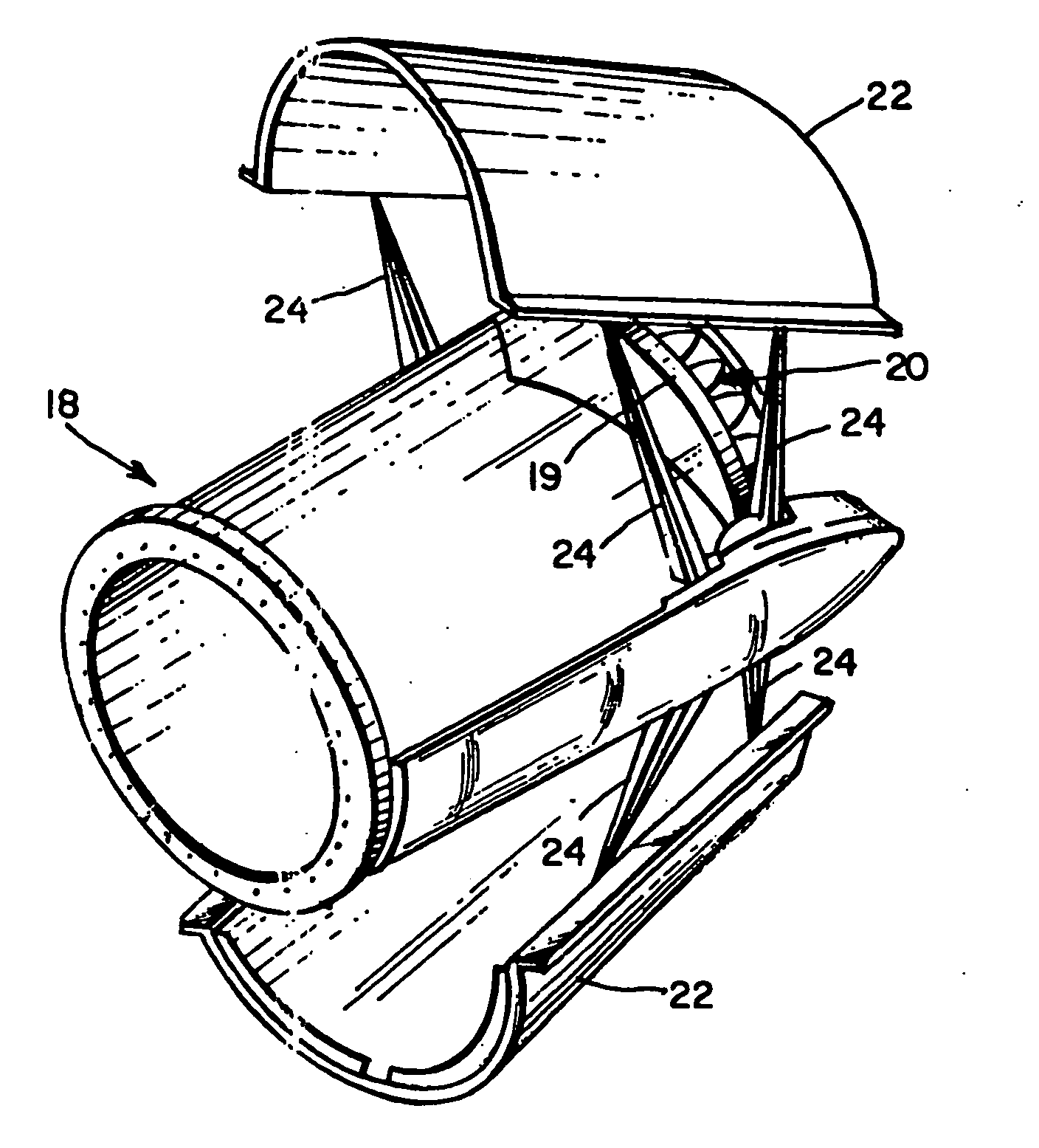
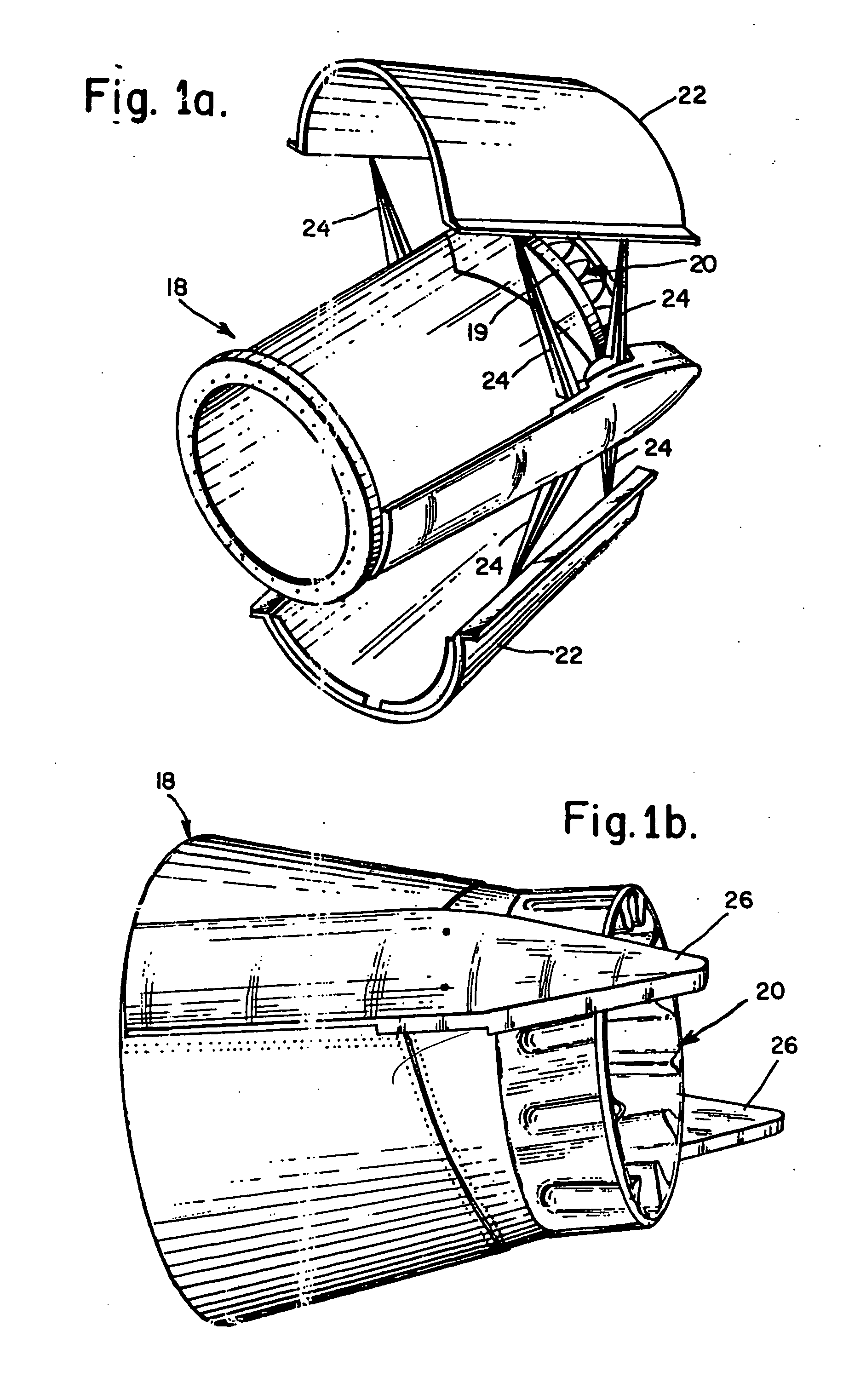
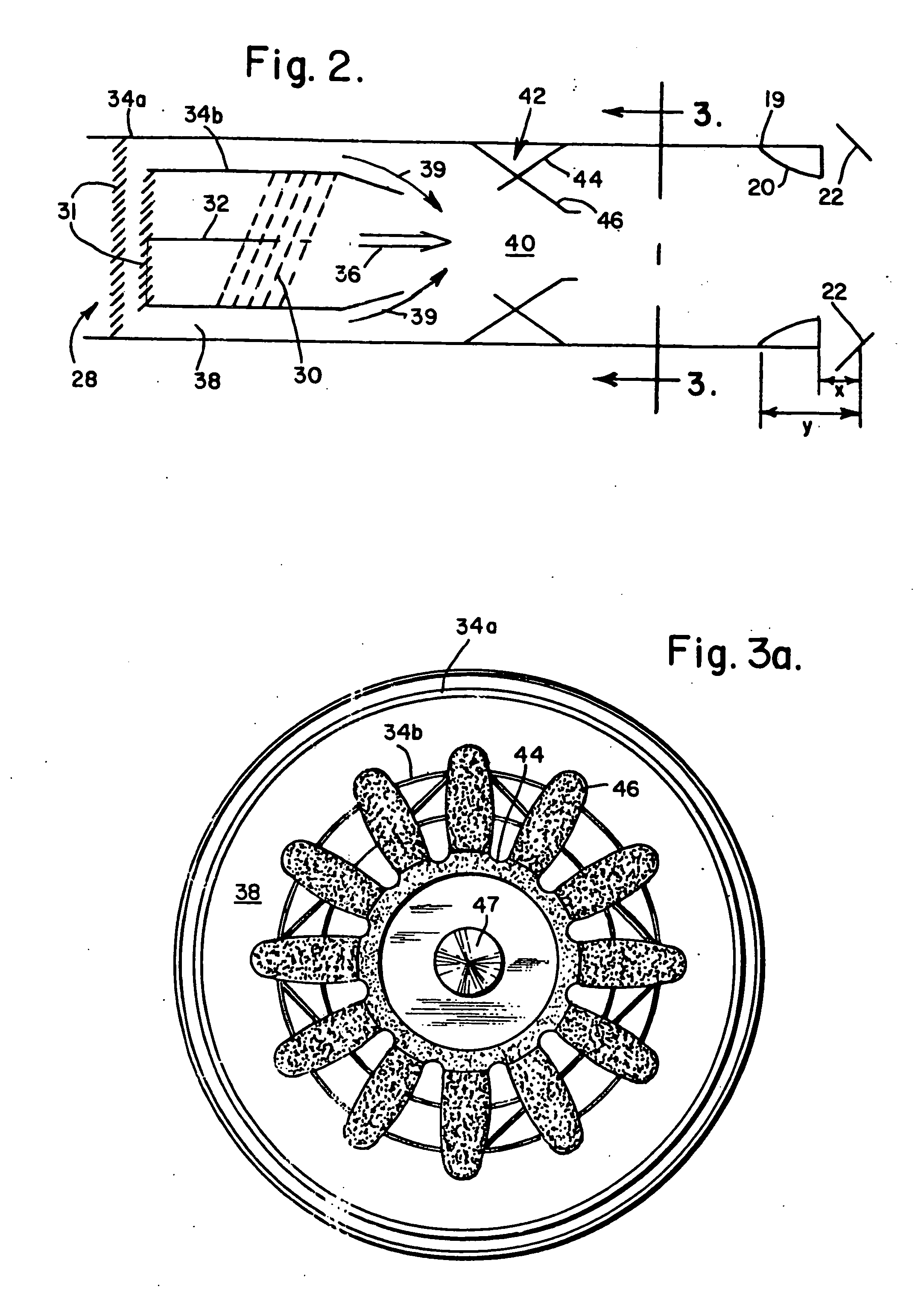
These and other problems are avoided and the Stage 4 / Chapter 4 requirements are both met and surpassed by the present invention, not only for the above-mentioned Pratt & Whitney JT8D-217 / 219 Series engine but also for other engines. The second stage or external jet nozzle mixer of the present invention includes a number of lobes, which may be equal in number to those of the first stage or internal mixer, and all of the second stage mixer lobes may be identically formed. As the lobes axially extend outwardly from the mixer attachment to the engine nozzle, they axially inwardly expand from an essentially circular base to an undulating configuration whose apices increase in height. The lobes include complex curvatures whose interior and exterior surfaces greatly enhance mixing respectively of the previously mixed bypass cooling air-hot exhaust gases from the internal mixer and additional ambient cooling air, and thereby also reduce noise. At their terminus, the area encompassed by the ...
PUM
 Abstract
Description
Claims
Application Information