Image forming optical system and electronic image pickup apparatus equipped with same
- Summary
- Abstract
- Description
- Claims
- Application Information
AI Technical Summary
Benefits of technology
Problems solved by technology
Method used
Image
Examples
example 1
[0489]
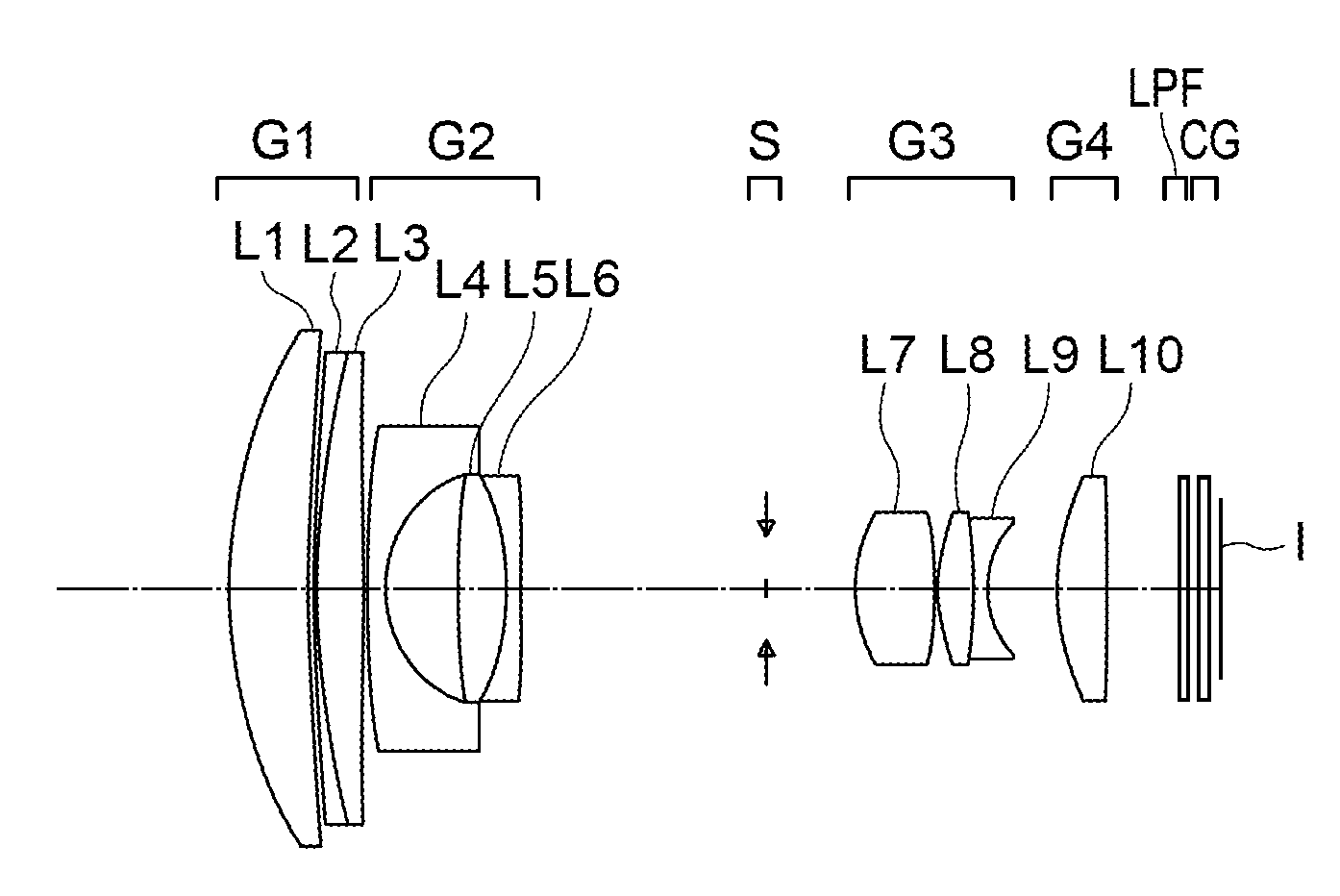
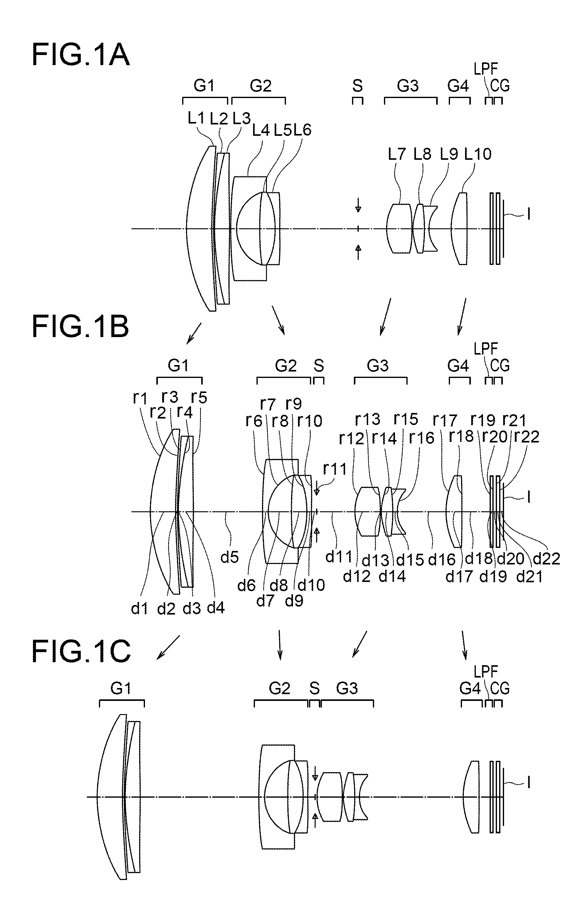
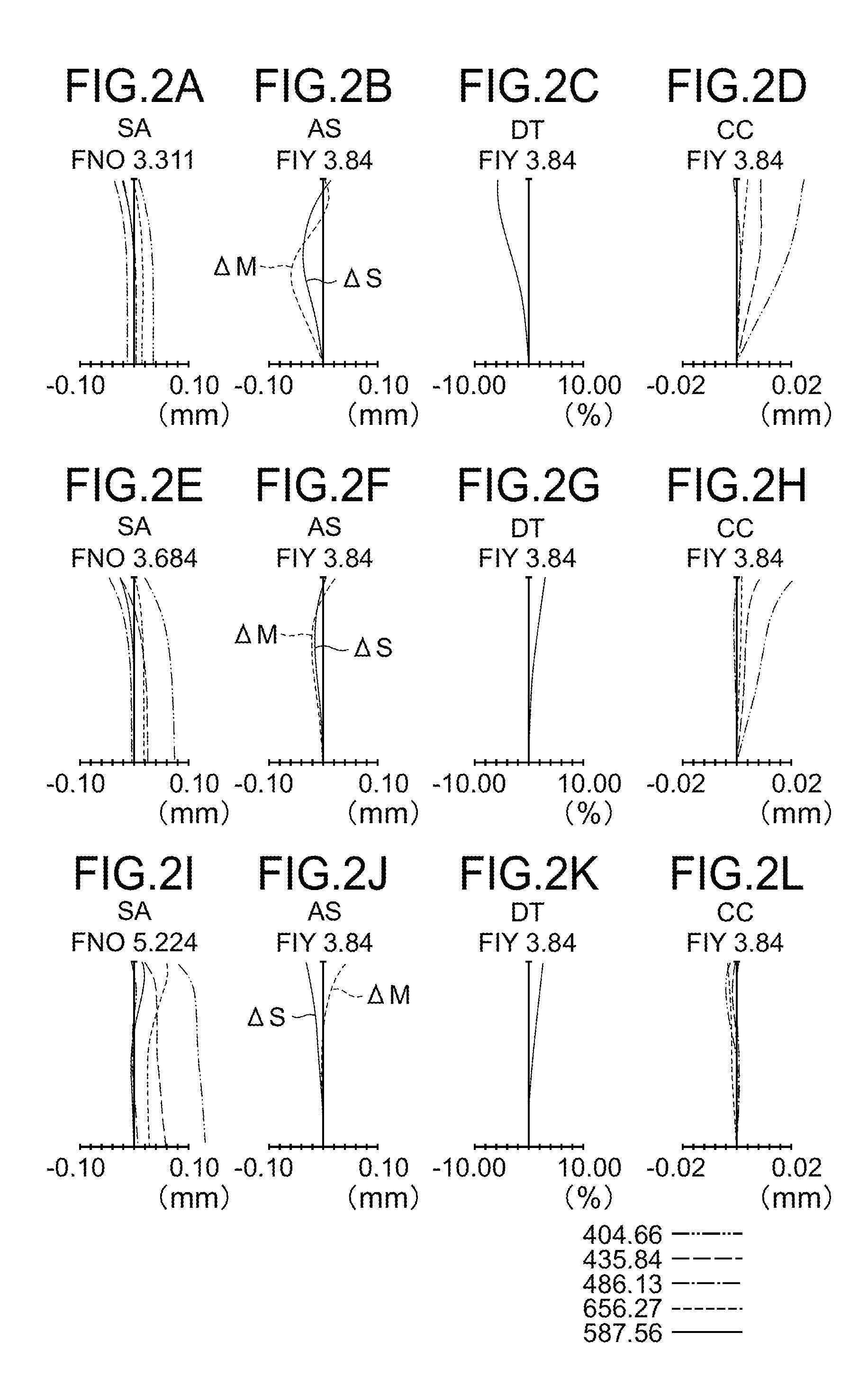
Unit mmSurface dataSurface nordndνdObject plane∞∞ 123.19773.52071.4970081.54 2148.05790.2000 3*107.46590.10001.6349423.22 4*35.00002.20001.6968055.53 5−554.5214Variable 6*59.59230.84001.8348142.71 75.21583.2299 834.83472.20001.8466623.78 9−12.25070.60001.7737747.1810*45.6624Variable11(Stop)∞Variable12*6.41563.69781.5891361.1413*−12.92340.1000149.55111.60001.8044039.5915−24.19770.65001.8051825.42164.4231Variable17*11.29452.20781.5307155.6918*1.855E+05Variable19∞0.40001.5477162.8420∞0.500021∞0.50001.5163364.1422∞0.4602Image plane∞Aspherical surface data3rd surfaceK = 0.,A2 = 0.0000E+00, A4 = −7.3531E−06, A6 = 2.5064E−08, A8 = 0.0000E+00,A10 = 0.0000E+004th surfaceK = 0.,A2 = 0.0000E+00, A4 = 1.9105E−05, A6 = −3.3995E−07, A8 = 0.0000E+00,A10 = 0.0000E+006th surfaceK = 0.,A2 = 0.0000E+00, A4 = 2.9908E−05, A6 = −5.3522E−07, A8 = 0.0000E+00,A10 = 0.0000E+0010th surfaceK = 0.,A2 = 0.0000E+00, A4 = −3.6654E−04, A6 = 3.9815E−06, A8 = −5.6860E−07,A10 = 0.0000E+0012th surfaceK = 0.,A2 = ...
example 2
[0490]
Unit mmSurface dataSurface nordndνdObject plane∞∞ 133.53021.00002.1435217.77 213.02002.8000 3∞10.80001.8061040.92 4∞0.2000 5*18.78962.80001.8830040.76 6*−20.02860.10001.7000020.00 7*−31.6031Variable 875.89200.50001.8348142.71 9*10.56411.500010−13.80380.50001.8061040.921113.46781.40001.9459517.9812−115.7257Variable13(Stop)∞Variable14*7.94292.50001.8348142.7115*−30.41910.1500169.69941.60001.6968055.5317−89.70380.50002.0006925.46185.4225Variable19*10.15941.60001.5307155.692054.6363Variable21*−14.99810.60002.1435217.772229.27402.20001.4874970.2323−7.15500.600024∞0.80001.5163364.1425∞0.7510Image plane∞Aspherical surface data5th surfaceK = 0.0655,A2 = 0.0000E+00, A4 = −9.2667E−06, A6 = 6.8548E−09, A8 = −8.0725E−09,A10 = 0.0000E+006th surfaceK = 0.0250,A2 = 0.0000E+00, A4 = −2.7424E−05, A6 = 1.8361E−07, A8 = −4.4513E−08,A10 = 0.0000E+007th surfaceK = −0.0507,A2 = 0.0000E+00, A4 = 4.8687E−05, A6 = −3.3335E−07, A8 = 7.0000E−09,A10 = 0.0000E+005th surfaceK = −0.9591,A2 = 0.0000E+00, A4 ...
example 3
[0491]
Unit mmSurface dataSurface no.rdndνdObject plane∞∞ 155.80911.00002.0006925.46 211.82141.7000 3∞9.50002.1435217.77 4∞0.2000 5*11.72830.10001.6900021.70 610.35982.80001.7432049.34 7−22.5466Variable 867.17760.50001.8040046.57 913.68320.400010−78.23890.50001.7880047.371129.67500.500012−12.31130.50001.7725049.60134.23371.00001.8081022.761411.2019Variable15(Stop)∞0.800016*9.64681.50001.5163364.1417−36.8259Variable18*17.51741.80001.7432049.3419−6.85390.50001.8081022.7620−13.6328Variable21−22.61230.60002.0950029.402219.91808.272823*22.51511.50001.5254056.2524−33.80103.471325∞0.80001.5163364.1426∞0.7967Image plane∞Aspherical surface data5th surfaceK = −0.0305,A2 = 0.0000E+00, A4 = −1.3222E−04, A6 = −4.8278E−07, A8 = −2.4643E−09,A10 = 0.0000E+0016th surfaceK = 0.1581,A2 = 0.0000E+00, A4 = −2.2541E−04, A6 = −8.4461E−06, A8 = 4.0248E−07,A10 = 0.0000E+0018th surfaceK = −0.2366,A2 = 0.0000E+00, A4 = −2.9206E−04, A6 = 2.7012E−06, A8 = −1.3860E−07,A10 = 0.0000E+0023rd surfaceK = −0.2751,A2 = ...
PUM
 Abstract
Description
Claims
Application Information
 - R&D
- Intellectual Property
- Life Sciences
- Materials
- Tech Scout
- Unparalleled Data Quality
- Higher Quality Content
- 60% Fewer Hallucinations
Browse by: Latest US Patents, China's latest patents, Technical Efficacy Thesaurus, Application Domain, Technology Topic, Popular Technical Reports.
© 2025 PatSnap. All rights reserved.Legal|Privacy policy|Modern Slavery Act Transparency Statement|Sitemap|About US| Contact US: help@patsnap.com


