

Optic System for Light Guide with Controlled Output
a technology of optical system and output light, which is applied in the direction of identification means, instruments, lighting and heating apparatus, etc., can solve the problems of poor technology efficiency, current art devices, excessive energy consumption, etc., and achieve the effect of accurate control of the angle of output light, simple construction and efficient transmission of ligh
- Summary
- Abstract
- Description
- Claims
- Application Information
AI Technical Summary
Benefits of technology
Problems solved by technology
Method used
Image

Examples
Embodiment Construction
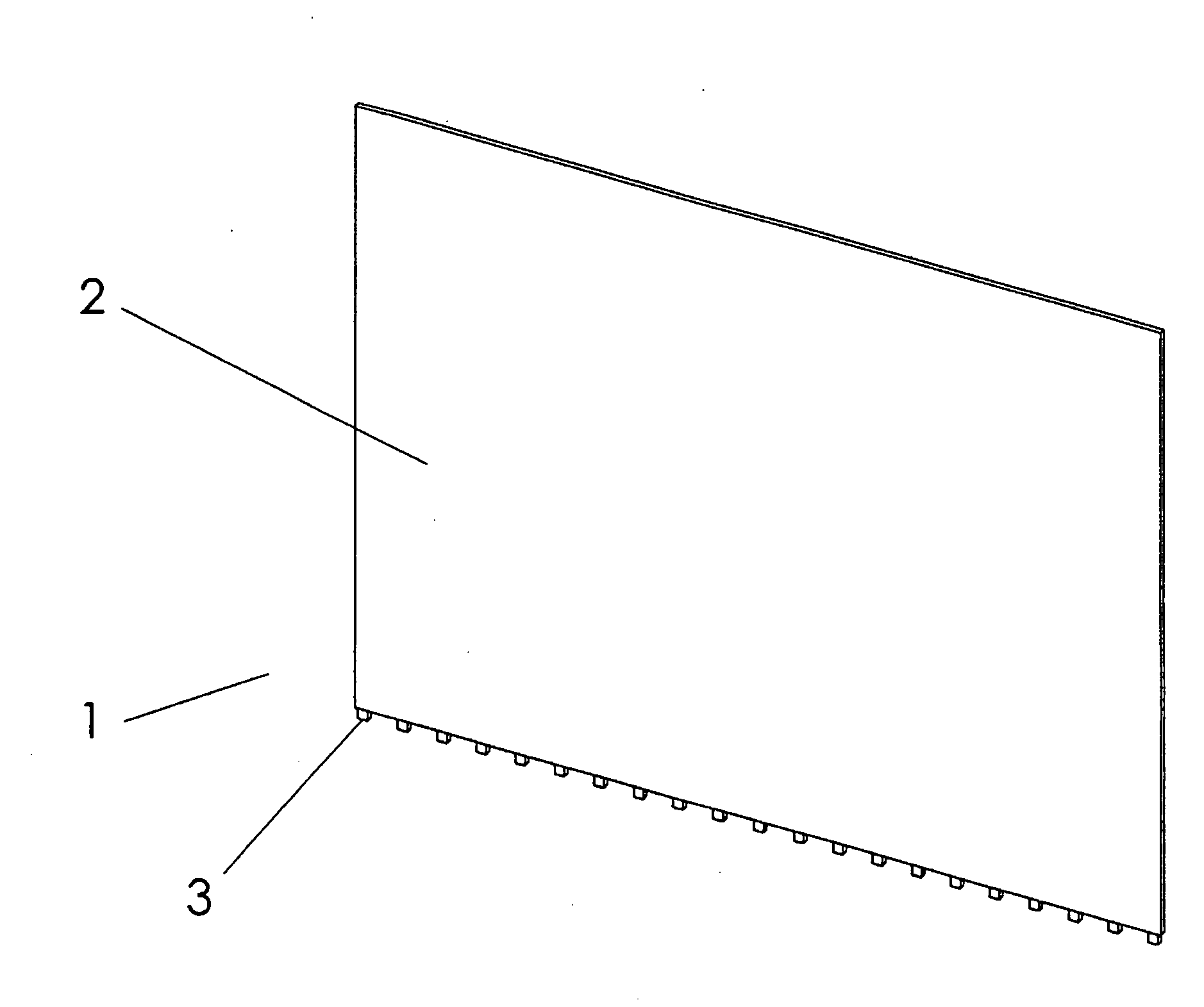
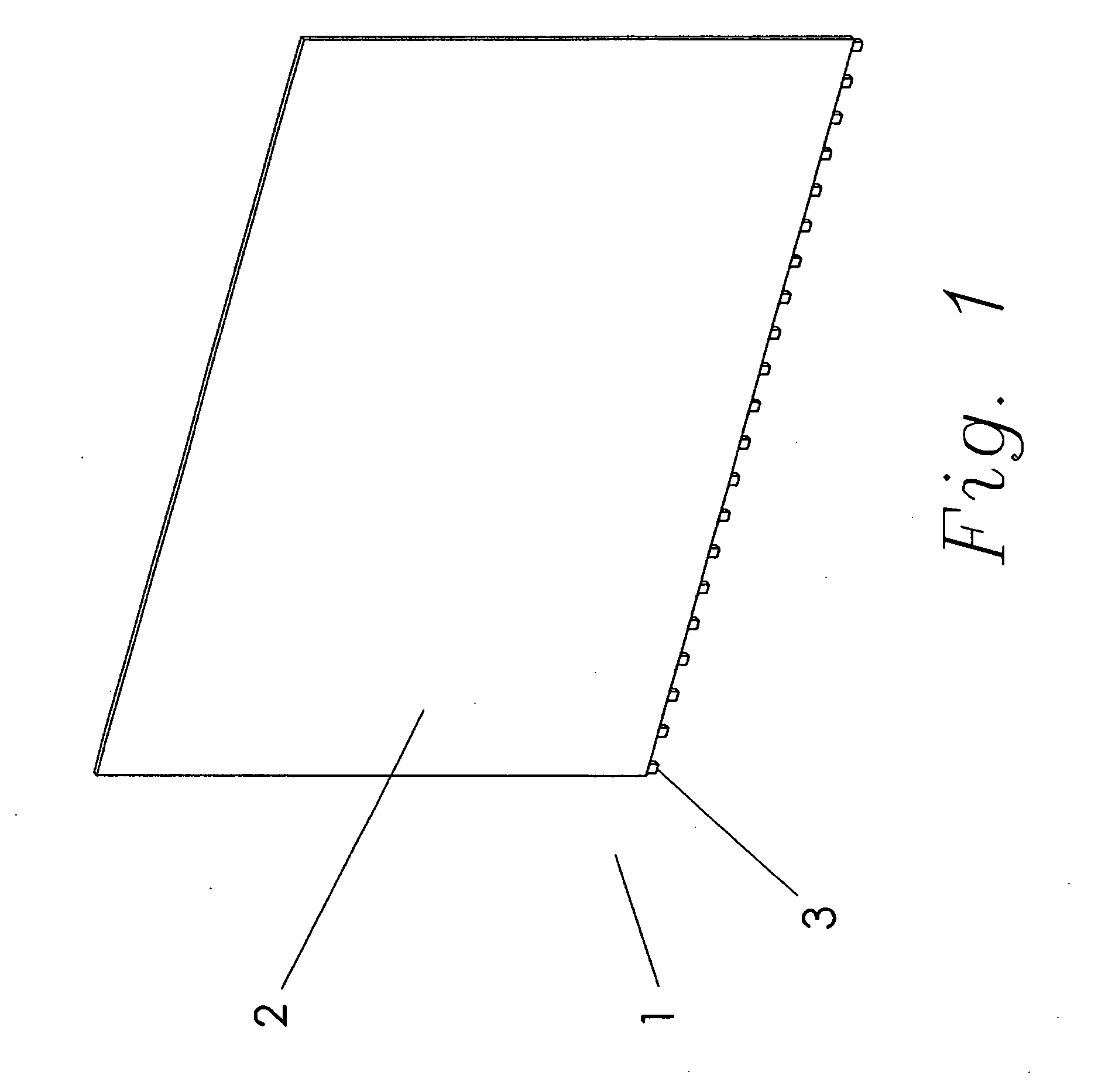
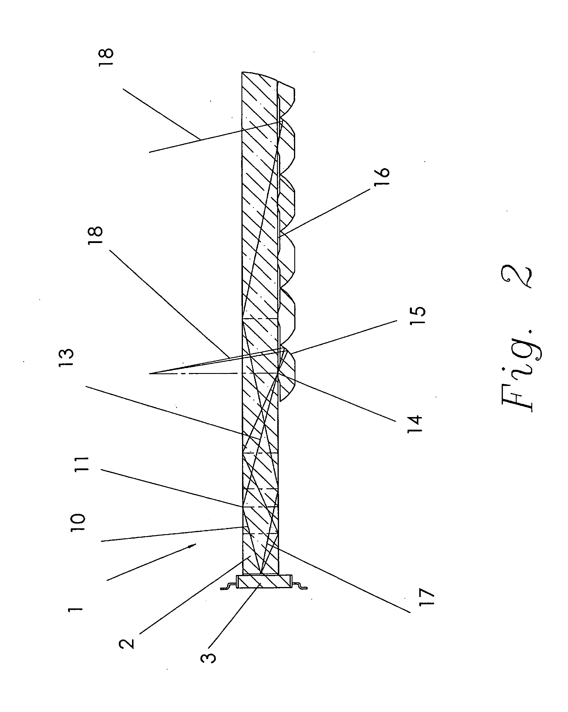
[0026]Referring first to FIG. 1, the light guide assembly 1 of the present invention comprises a light guide 2 with a planar surface and a plurality of LEDs 3. The LEDs 3 may be located along a surface, such as a lower edge of the light guide 2. The number of colors of LEDs 3 and the side of the light guide 2 where the LEDs 3 are located may be a function of the size, shape and application of the light guide 2. The LEDs 3 may be situated on more than one side of the light guide 2. The LEDs 3 may require electronics to drive them at the proper level. A person knowledgeable in LED driver electronics could devise many different circuits to accomplish this task. The embodiment illustrated in FIG. 1 comprises a total of 27 LEDs 3 shown generally equally spaced along the bottom edge of the light guide 2. It should be recognized that other types of light sources such as a laser, incandescent light, fluorescent light, or even natural light, could suffice in the place of the LEDs 3.
[0027]The...
PUM
 Abstract
Description
Claims
Application Information