Optimizing a receiver for multiple antenna configurations

Inactive Publication Date: 2011-11-03
QUALCOMM INC
View PDF2 Cites 13 Cited by
  • Summary
  • Abstract
  • Description
  • Claims
  • Application Information

AI Technical Summary

Benefits of technology

[0006]The Cholesky decomposition matrix determination and the whitening matrix determination may reuse at least one function call more than once. The Cholesky decomposition matrix determination may use function calls A(a0,a1,a2,a3)=√{square root over (real(a0)−(a12+a22+a32))}{square root over (real(a0)−(a12+a22+a32))},
[0007]The whitening matrix determination may include recursively determining the whitening matrix based on a noise covariance matrix that is smaller than the whitening matrix. During the recursive algorithm, an upper left quadrant of the whitening matrix may be calculated based on an upper left quadrant of the noise covariance. An inverse of the upper left quadrant of the noise covariance may be calculated based on the upper left quadrant of the whitening matrix. A first intermediate 2×2 matrix may be calculated based on the inverse of the upper left quadrant of the noise covariance and a lower quadrant of the noise covariance. A second intermediate 2×2 matrix may be calculated based on a lower right quadrant of the noise covariance, the first intermediate 2×2 matrix and the lower left quadrant of the noise covariance. A lower right quadrant of the whitening matrix may be calculated based on the second intermediate 2×2 matrix. A lower left quadrant of the whitening matrix may be calculated based on the lower right quadrant of the whitening matrix and the first intermediate 2×2 matrix.

Problems solved by technology

However, these techniques may depend on propagation environments and the configuration of other devices.

Method used


Image

  • Optimizing a receiver for multiple antenna configurations
  • Optimizing a receiver for multiple antenna configurations
  • Optimizing a receiver for multiple antenna configurations

Examples


Embodiment Construction

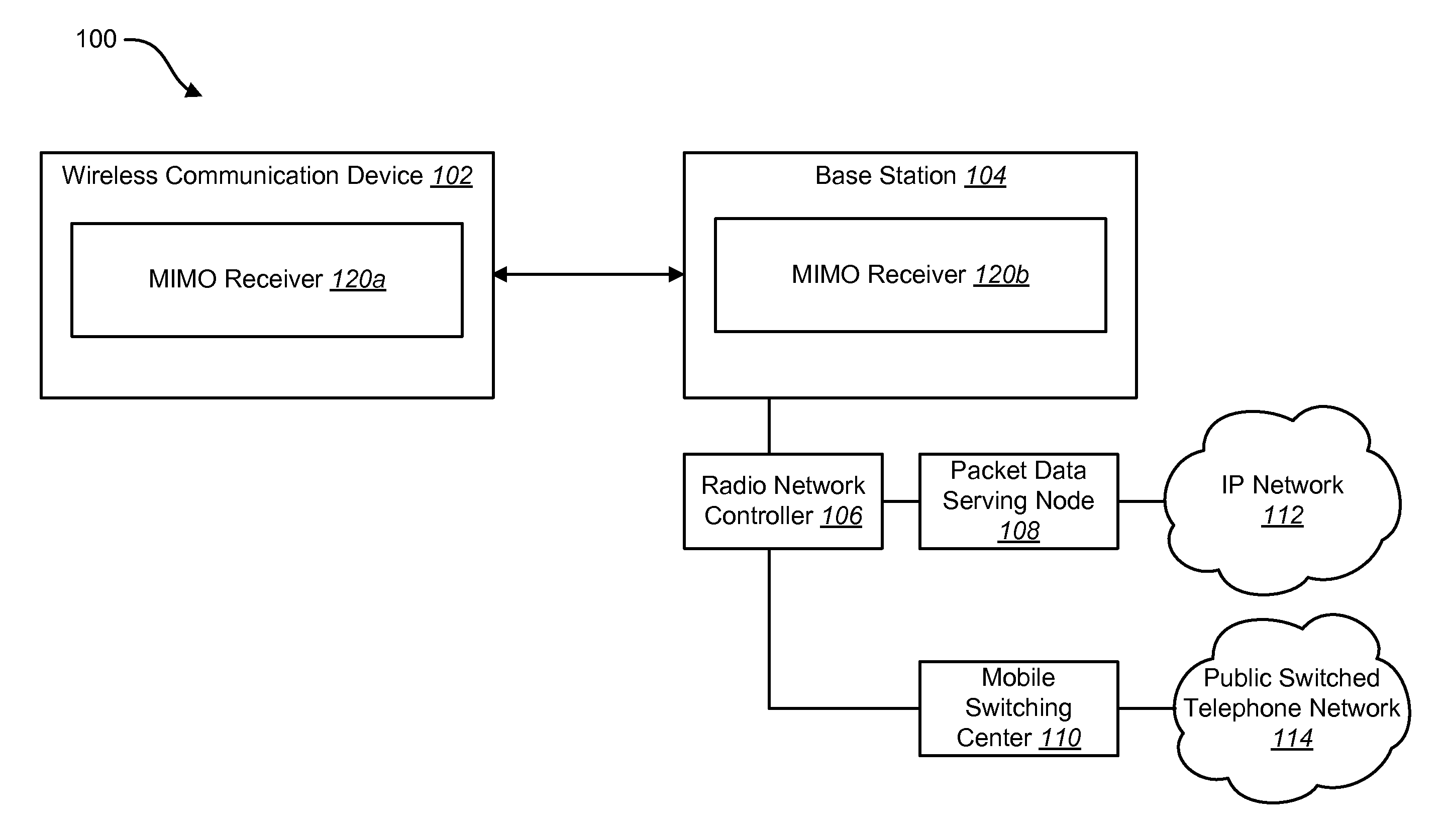
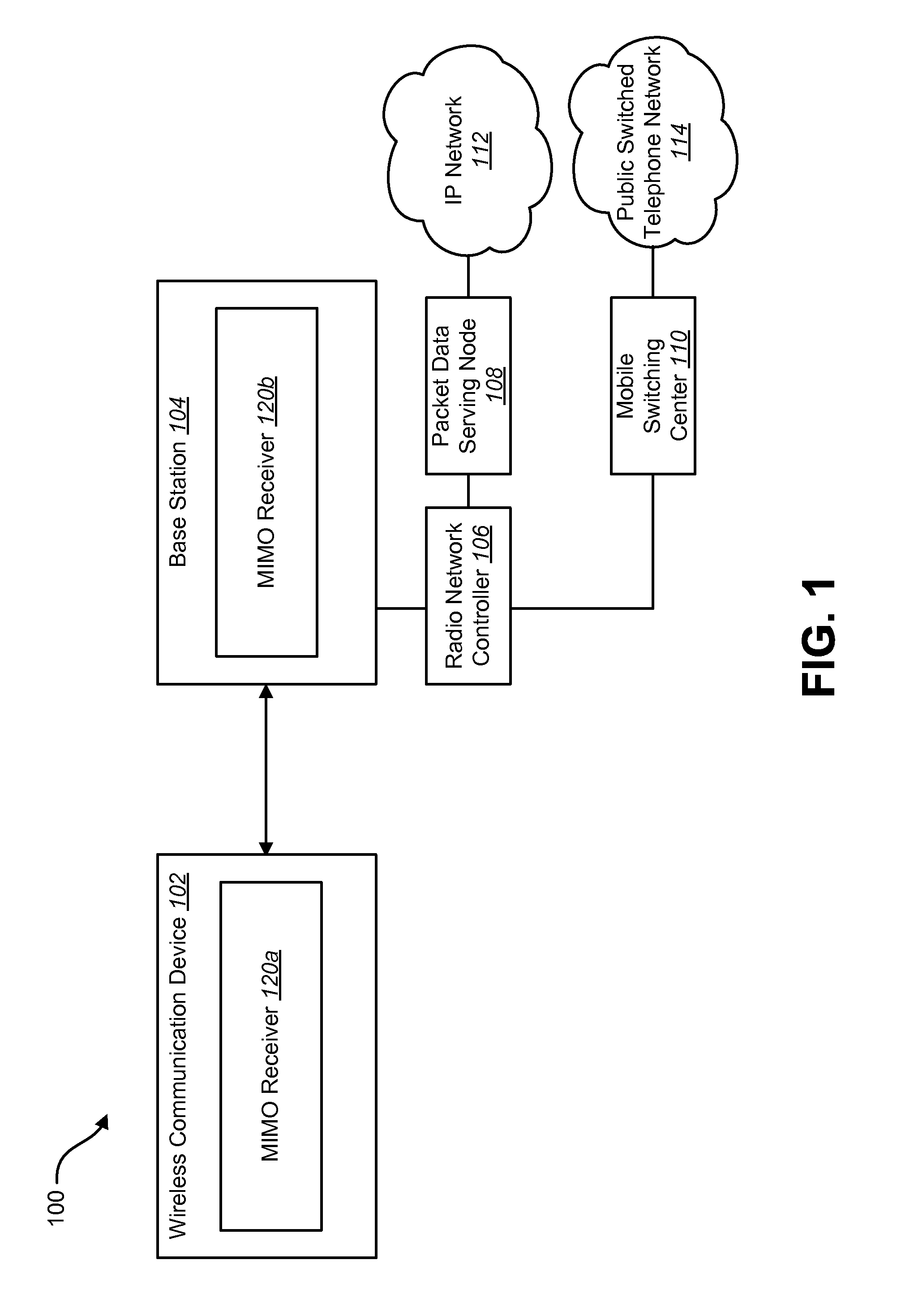
[0025]For next generation wireless systems, antenna arrays may be deployed for both wireless communication devices and base stations. This may enable advanced transmission and reception techniques, such as Single User Multiple Input Multiple Output (SU-MIMO), Spatial Division Medium Access (SDMA), etc. In Long Term Evolution (LTE), for example, Multiple Input Multiple Output (MIMO) techniques may be considered for both uplink and downlink in Frequency Division Duplexing (FDD) systems and Time Division Duplexing (TDD) systems.

[0026]These signal processing techniques may involve beam forming or multiplexing of different transmission data streams. This may result in different antenna configurations. For example, in commercial Multiple Input Multiple Output (MIMO) systems, two antenna configurations are commonly used: pairs of cross-polarized antennas and closely spaced antenna arrays. The cross-polarized antenna arrays may be used to minimize antenna correlations. This may be common fo...


PUM


Abstract

A method for optimizing a multiple input multiple output (MIMO) receiver for multiple antenna configurations is disclosed. A noise covariance is determined based on a noise estimate of a wireless signal. A Cholesky decomposition matrix is determined based on the noise covariance. A whitening matrix is determined based on the Cholesky decomposition matrix. The wireless signal is whitened using the whitening matrix.

Description

RELATED APPLICATIONS[0001]This application is related to and claims priority from U.S. Provisional Patent Application Ser. No. 61 / 328,834, entitled “Optimizing a Receiver for Multiple Antenna Configurations”, filed Apr. 28, 2010, and assigned to the assignee hereof and hereby expressly incorporated by reference herein.TECHNICAL FIELD[0002]The present disclosure relates generally to communication systems. More specifically, the present disclosure relates to optimizing a receiver for multiple antenna configurations.BACKGROUND[0003]Wireless communication systems have become an important means by which many people worldwide have come to communicate. A wireless communication system may provide communication for a number of mobile devices, each of which may be serviced by a base station. Examples of mobile devices include cellular phones, personal digital assistants (PDAs), handheld devices, wireless modems, laptop computers, personal computers, etc.[0004]As wireless communication becomes...

Claims


Application Information

Patent Timeline
Patent Type & Authority Applications(United States)
IPC IPC(8): H04L27/06
CPCH04B7/0413H04L1/20H04B7/10H04L25/0224H04L25/0246H04L25/0204
Inventor XU, HAOFUCHS, ROBERT JASONLIU, KECORONA, JAMESFAN, ZHIFEI
Owner QUALCOMM INC
Why Eureka
Try Eureka